J:\Etude-3d\Aquaset\0-DOSSIER TECHNIQUES\1-sw-plaisance\ESW\00-ESW 0707\09- Manuels Utilisateur\DOC UTILISATEUR ESW FRUKES 2009-10-C.doc VERSION 2009-10-C FR/UK/ES Page 23/58
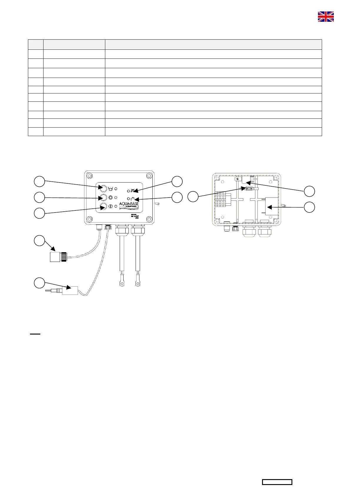
3.4 – ELECTRIC DRAWING AND CONTROL PANEL
REP. DESCRIPTION FONCTION
14* Valve connector Connection of the discharge valve to the salinometer card.
17 Salinometer cell Measures the salinity of the produced water with a cell.
30 Green selector switch Starting up of the unit and lighting up of the green indicator lamp.
31 Red selector switch Stopping of the unit.
32 Discharge signal lamp Red LED indicating that the reject valve is in « discharge » position.
33 Production signal lamp Green LED indicating that the reject valve is in « production » position.
34 Main breaker Protection of the electric motor if overload. General power off.
36 Fuse minifuse Protection salinometer card.
37 Power relay KM1 Feeding electric motor.
41 Blue selector switch Stopping of the production and starting up of the rinsing semi-automatic temporized cycle.
It is recommended to install the control panel near to the unit to facilitate the maintenance.
NB: it is possible to install a remote control (see following page)
30
41
31
14*
17
33
32
36
37
34
 Loading...