28
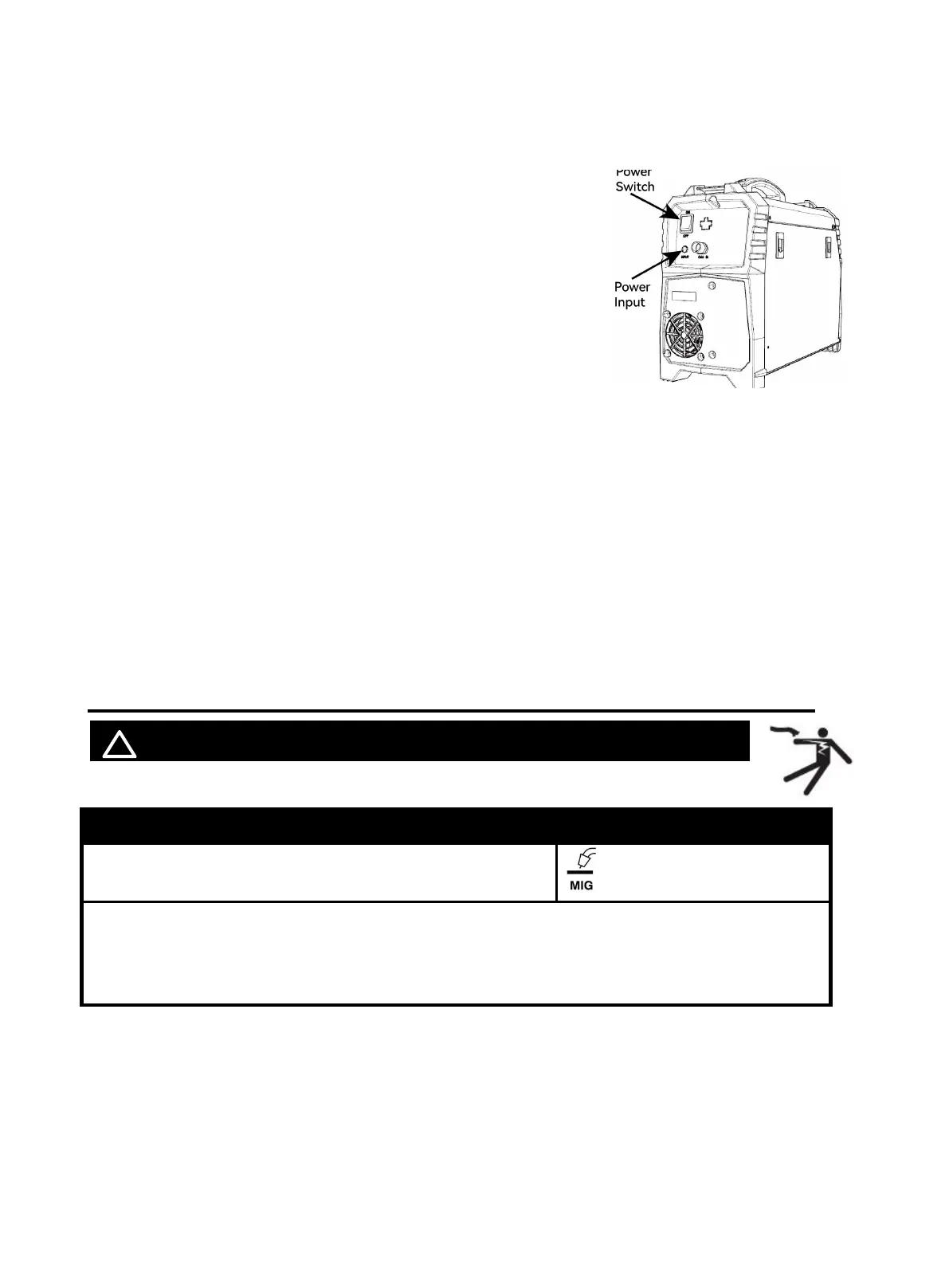
properly grounded. Set MIG Gun down on nonconductive, nonflammable surface away
from any grounded objects. And then then turn the Power Switch ON.
NOTE:
For optimal performance, connect the MIG250 to a 50A branch
circuit. If connected to a circuit with lower capacity, expect
reduced welding current and duty cycle. The circuit must be
equipped over 50A with delayed action-type circuit breaker or
fuses.
Ensure the mains supply voltage remains within ±15% of the
rated value. Low voltage can lead to subpar welding results,
while excessively high voltage may cause components to
overheat and potentially fail. Check whether the voltage value
varies in acceptable range with a multi-meter.
Code Requirements for Electrical Input Connections
This welding machine must be connected to a power source in accordance with applicable electrical
codes. The National Electrical Code provides standards for amperage handling capability of supply
conductors based on duty cycle of the welding source.
NOTICE: Do not remove the power cord ground prong.
If there is any other question about the installation meeting applicable electrical code requirements,
consult a qualified electrician.
7.3 Wire Stick Out
! WARINING BEWARE OF ELECTRIC SHOC K!
Description Picture
1.Set the Mode Switch to MIG setting.
2. Inching
In MIG mode, not during welding, press torch trigger for at least 3S, the welder will go in fast
inching status, closing output port voltage and gas valve. Release torch trigger,the welder will stop
inching.
Figure 40
https://www.arccaptain.com/