28 Quick Start Guide: 7500N Series Modular Switches
Cabling the DC Power Supply Chapter 4: Cabling the Modular Switch
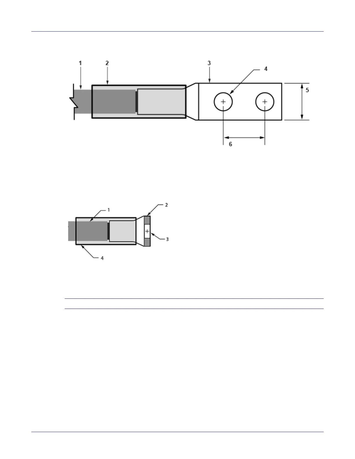
Figure 4-2: Lugs wiring terminations
Figure 4-3: Ground lug wiring termination (PWR-2700W-DC-R)
Note You can also use a 45° angled connector instead of the straight connector shown.
Step 2 Use agency-approved compression (pressure) lugs for wiring terminations with a single 5/16"
mounting hole. Two-hole lugs should have 1/4" mounting holes on 5/8" centers.
The PWR-2700W-DC-R ground lug is a right-angle lug. Check the terminations for the
appropriate wire size. Use a ground wire of at least 2 – 4 AWG. Use only copper wire.
Step 3 Slip on heat-shrink tubing on the wire ends before assembling the lugs on to the wire.
• The lugs must be crimped with the proper tool.
• The tubing should extend over the lug’s barrel and the wire's insulator.
Step 4 Shrink the tubing with a heat gun.
4.4.3 PWR-3K-DC-RED Power Supply
Figure 4-4 displays the PWR-3K-DC-RED power supply.
1 Insulated wire 3 -48V + RTN lug 5 1/2”
2 Heat-shrink tubing 4 1/4” 6 5/8”
1 Insulated wire 3 5/16” Ø
2 Ground lug (right angle) 4 Heat-shrink tubing