Chapter 4: Cabling the Modular Switch DC Power Adapter Installation for PWR-2700-DC-R
Quick Start Guide: 7500N Series Modular Switches 29
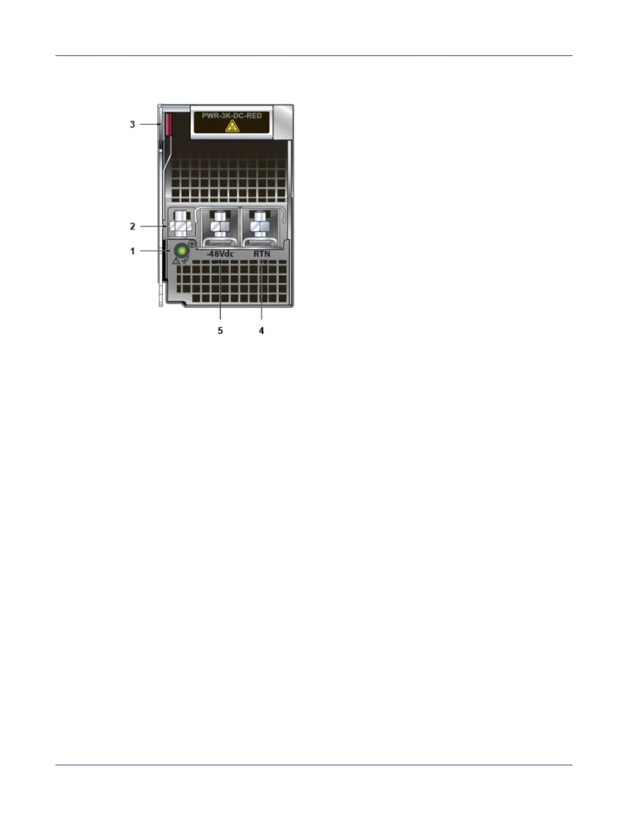
Figure 4-4: PWR-3K-DC-RED power supply
Step 1 Prepare the stranded wiring, see Section 4.4.2
Step 2 Attach the power cable to the supply terminals.
Step 3 Tightening Torque: 2.7 N-m (24 in.-lbs.)
4.5 DC Power Adapter Installation for PWR-2700-DC-R
4.5.1 Connecting the Power Cable Lug to the Terminal Studs
Step 1 Prepare the stranded wiring, see Section 4.4.2.
Step 2 Remove the clear plastic cover protecting the terminal studs on the adapter by lifting the small
center tab while sliding the cover off the adapter.
4.5.2 Connecting the Ground to PWR-2700-DC-R Power Supply
The primary ground on the system requires a 2 – 4 AWG 5/16 inch lug per power supply.
Figure 4-5 displays the PWR-2700-DC-R power supply without the DC adapter.
1 Status LED 3 Ejector 5 -48V terminal
2 Ground terminal 4 RTN terminal