Chapter 3: Rack Mounting the Switch 7504N and 7508N Rack Mounting
Quick Start Guide: 7500N Series Modular Switches 13
Step 4 A minimum of four screws is required on each side of the chassis. The accessory kit provides
screws that fit many common equipment racks. When installing the switch into a rack with
unthreaded post holes, nuts are also required to secure the switch to the rack posts.
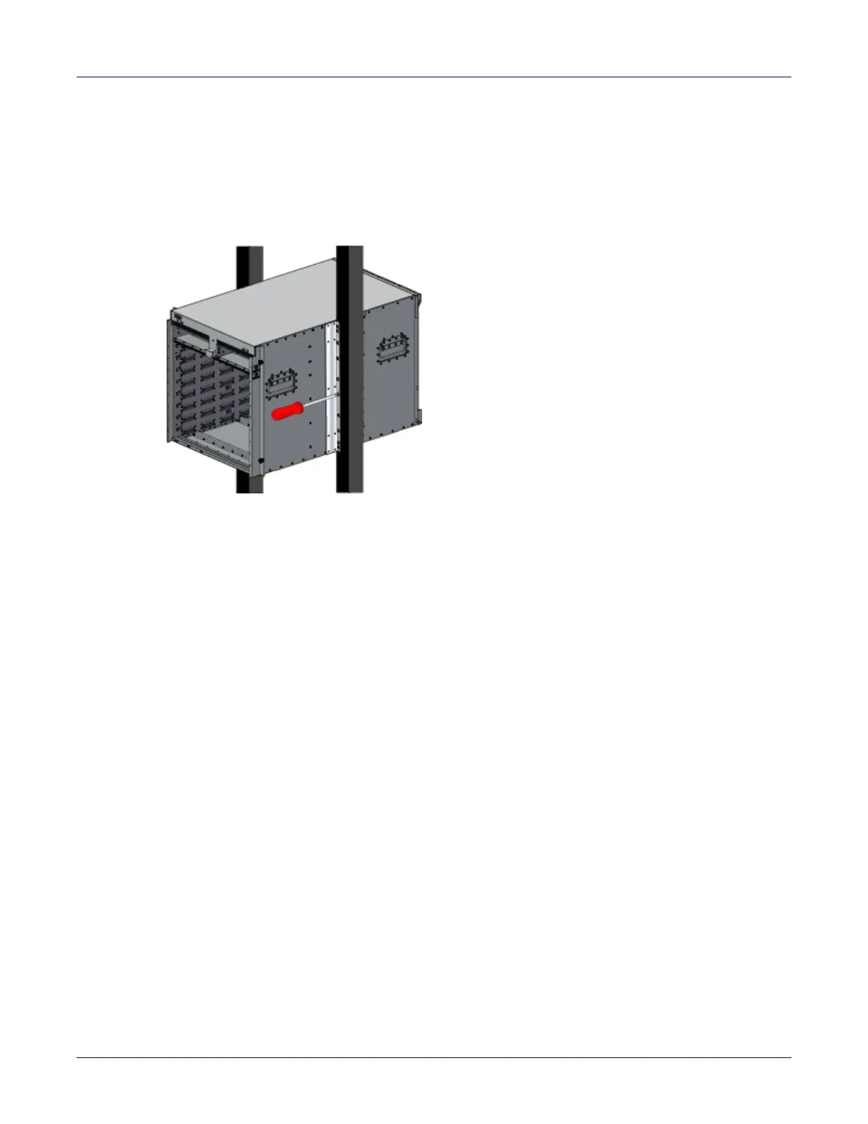
Step 5 Attach the bracket flanges to the rack posts (Figure 3-3 on page 13). Space the screws evenly
along the flange.
Figure 3-3: Attaching flanges to the rack post
Step 6 After completing the two-post installation, proceed to Chapter 4.
3.1.4 Four-Post Rack Mount
The switch is mounted onto a four-post rack by assembling a shelf into the rack, then placing the switch
on the shelf.
Illustrations in this chapter depict the mounting of an unpopulated 8-slot chassis.
The accessory kit provides the following four-post mounting parts:
• 2 front brackets
• 4 shelf supports
• 2 back brackets (not needed for racks with threaded holes)
•left shelf
• right shelf
Figure 3-4 on page 14 displays the front four-post mounting parts. Figure 3-5 on page 15 displays the
rear four-post mounting parts.
3.1.5 Assembling the Shelf
Step 1 Attach the front bracket and shelf support to the left front rack post, as shown in Figure 3-4 on
page 14. An up arrow is printed on the shelf support to indicate its proper orientation.
Unthreaded rack holes: Use the M6 screws and cage nuts supplied in the accessory kit.
Threaded rack holes: Attach the front bracket to the post with screws that can be threaded
through the rack post.
Step 2 Secure the shelf support to the post with nuts that fit the screws threaded through the post.
 Loading...