Appendix A: Status Indicators Line Card Module Indicators
Quick Start Guide: 7500N Series Modular Switches 43
Component Activity Status LEDs
LEDs located below the vents and left of the input ports display summary indicators for power supplies,
fabric modules, fans, and line cards. Table A-2 interprets the states of these indicators. When error
conditions are indicated, refer to LEDs on the specified modules to determine the condition’s source.
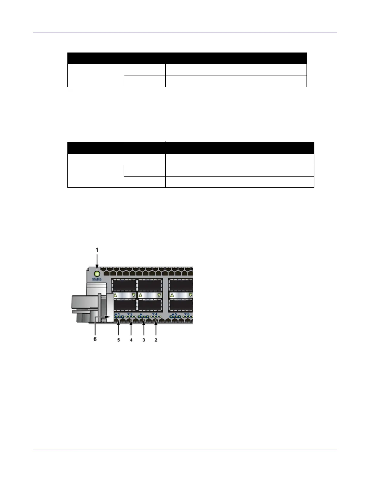
A.2 Line Card Module Indicators
Each line card module provides one status LED plus LEDs for each port on the card. The figures in
Appendix E indicate the location of the LEDs on each line card.
Figure A-4: Line card Status LED
Active Off Not active.
Green Active and controlling the switch.
Table A-2 Component activity LED states
LED Name LED State Module State
Power Supply,
Line Card
Fabric Module
Fans
Off No modules are present or powered.
Green All powered modules are operating normally.
Red One or more components failed.
Table A-1 Supervisor activity LED states (Continued)
LED Name LED State Supervisor State
1 Status LED 4 QSFP port 2 LEDs
2 QSFP port 4 LEDs 5 QSFP port 1 LEDs
3 QSFP port 3 LEDs 6 10G / 40G /100G QSFP port LEDs