42 Quick Start Guide: 7500N Series Modular Switches
Supervisor Module Appendix A: Status Indicators
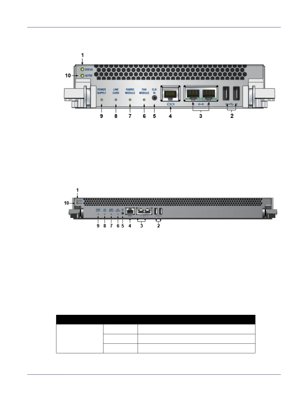
Figure A-2: Supervisor 7500-SUP 2
Figure A-3: Supervisor 7500E-SUP
Supervisor Activity Status LEDs
The Status and Active LEDs are located on the left side of the Supervisor Module. Table A-1 interprets
the states of these two LEDs.
1 Status LED 5 Clock input port (optional) 9 Power supply status LED
2 USB ports 6 Fan module status LED 10 Active LED
3 Ethernet management
ports
7 Fabric module status LED
4 Serial console port 8 Linecard status LED
1 Status LED 5 Clock input port (optional) 9 Power supply status LED
2 USB ports 6 Fan module status LED 10 Active LED
3 Ethernet management
ports
7 Fabric module status LED
4 Serial console port 8 Linecard status LED
Table A-1 Supervisor activity LED states
LED Name LED State Supervisor State
Status Off No power, failed, or improperly inserted.
Green Operating normally.
Red Supervisor failed.