44 Quick Start Guide: 7500N Series Modular Switches
Fabric Status Indicators Appendix A: Status Indicators
Table A-3 interprets the states of the status LED.
The line card provides LEDs for each port module socket:
• Each LED corresponds to a module.
• A set of four LEDs correspond to each module. When the module is programmed as a 40G port,
the first LED in the set reports status. When the module is programmed as four 10G or 100G ports,
each port is assigned to an LED within the set.
Table A-4 interprets the port LED states.
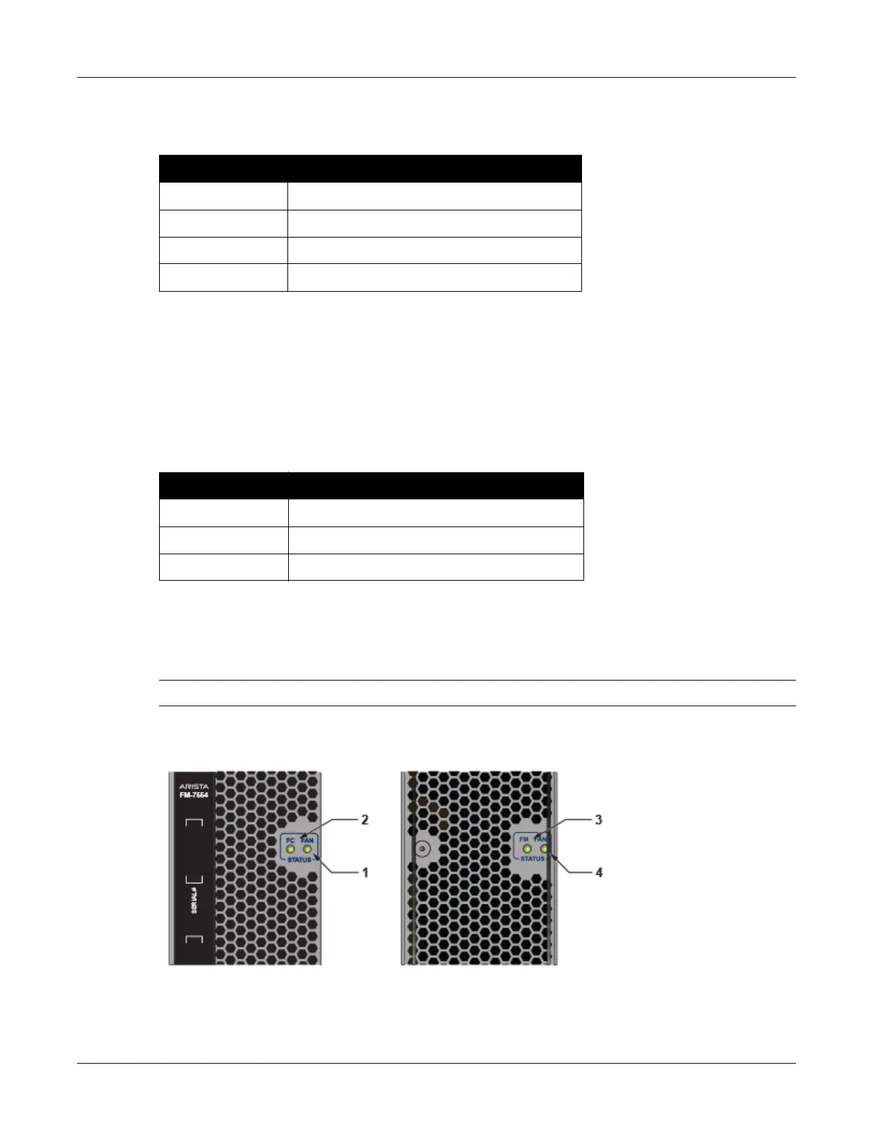
A.3 Fabric Status Indicators
Fabric Status LEDs are on fan-fabric modules. Appendix D displays the position of these LEDs on the
rear of each switch. Figure A-5 on page 44 displays fan status and fabric status LEDs on the switch.
Note Gen 1 Fabric modules are not supported.
Figure A-5: 7504N (left) and 7508N fan status and fabric status LEDs
Table A-3 Line card status LED states
LED State Status
Off Line card not inserted.
Green Line card operating normally.
Yellow Line card administratively shut down.
Red Line card has failed.
Table A-4 Line card Port LED States
LED State Status
Off Port link is down.
Green Port link is up.
Yellow Port is disabled in software.