Appendix F: Maintenance and Field Replacement Touch Point Shield (Optional)
Quick Start Guide: 7500N Series Modular Switches 77
•For 7504 and 7508, unscrew the two Phillips screws on the back of the fabric module. Rotate
the ejector handle(s) 90 degrees back to hard stops and pull fabric module straight back to
remove. Install the replacement fabric module by first opening the ejector handle(s), then
aligning the module in its slot with the same orientation as the original, and sliding it into
the slot in the same orientation as the one removed. When the module is seated, rotate the
ejector handle(s) forward and fasten the Phillips screws.Do not overtighten Phillips screws.
•For 7512 the failed fan replacement requires the removal of the plastic safety guard in addition
to the fabric module. First, in the CLI console, enter the global configuration mode by issuing
the commands enable, then config, followed by env fan-speed override 100 to increase fan
speeds. Wait five minutes for the system to sufficiently cool. Unscrew the six captive screws
on outside perimeter of plastic safety guard. Set safety guard aside. Fabric module removal
and reinstallation procedure is same as 7504/7508 instructions above. Caution, 7512R fabric
module weighs more than 25lbs. Support module during handling. Reinstall plastic safety
guard and fasten the six captive screws. Issue the env fan-speed auto command in the CLI
console for normal operation.
F.3 Touch Point Shield (Optional)
F.3.1 Installing the Touch Point Shield
The 7512N supports an optional Touch Point Shield component that is attached to the rear of the
device. Perform the following steps to install the Touch Point Shield to the 7512N.
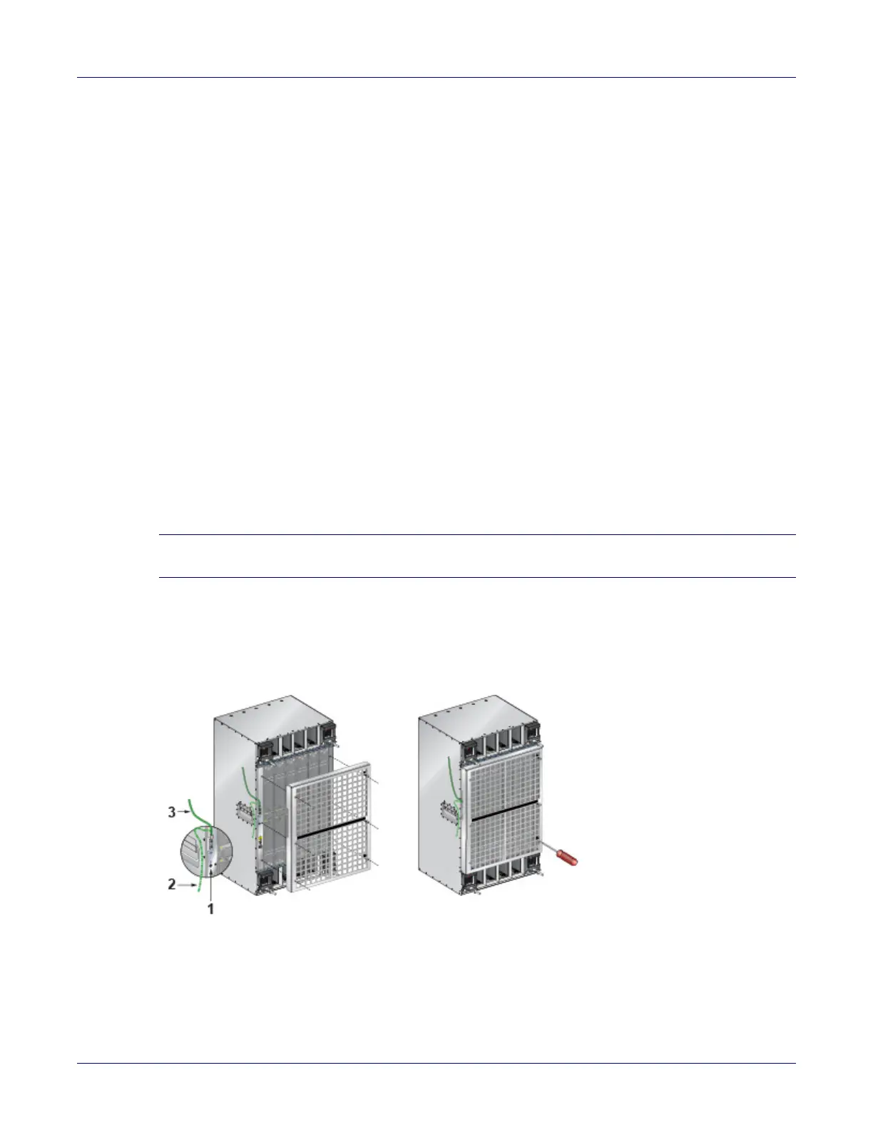
Step 1 Attach the ground cable to the chassis.
Note The ground cable should be attached so that it exits upwards to enable access to the ESD port on the
chassis. You may arc the ground cable downwards, if needed (Figure F-2).
Step 2 Match the six screws on the Touch Point Shield to the holes on the chassis and screw in the
Touch Point Shield as shown in (Figure F-2).
Figure F-2: Installing the Touch Point Shield (7512N)
1 ESD port 3 Ground cable going up
2 Ground cable going down