installation &
operating instructions
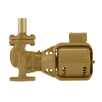
Design Envelope 4322 & 4372
Tango Pumping Unit
23
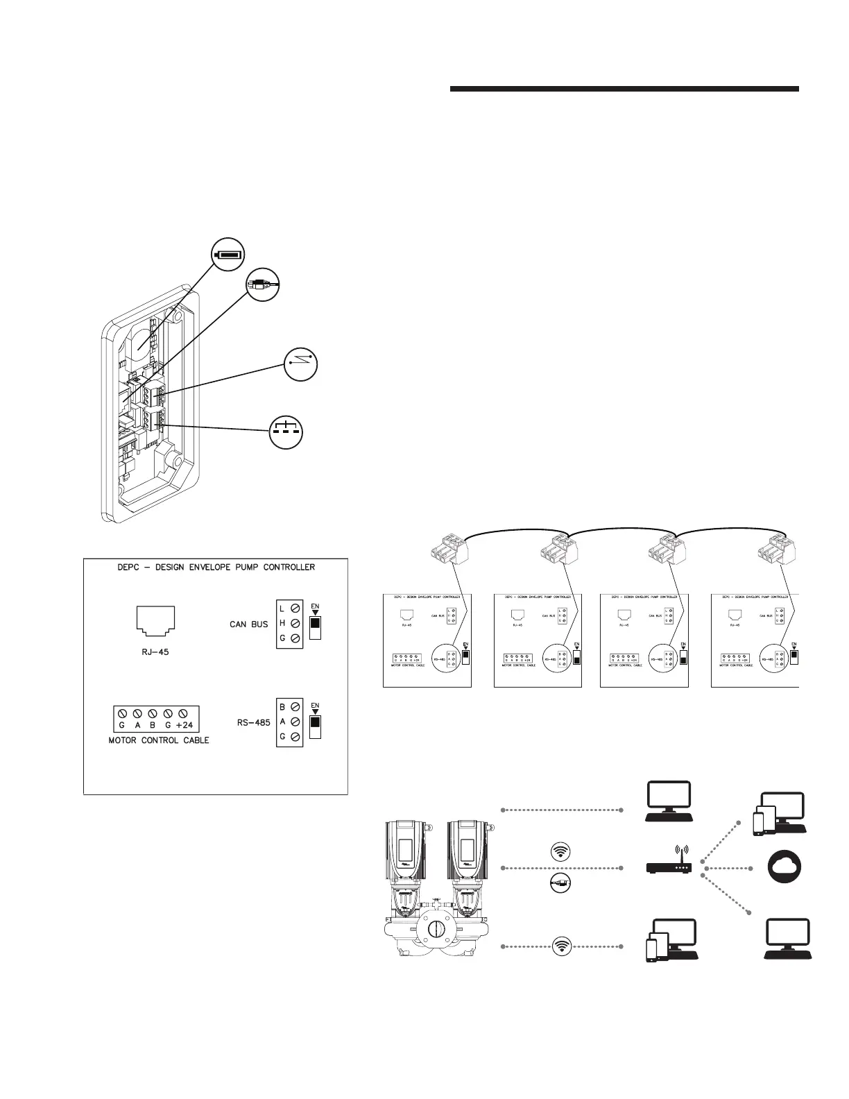
2.4.3 can bus wiring
The CAN bus port on the depc has terminals for the following signal
connections: High, Low, and Ground, as shown in fig. 2.4a. If multiple
pumps are connected in parallel for CAN bus (supplied by others) they
should be daisy chained together. Ensure that only the first and last
terminating resistor switches are set to Enabled.
2.4.4 rs 485 wiring
For a BACnet ms/tp or Modbus rtu connection to a building automation
system, connect the network cable to the rs-485 port, as shown in fig.
2.4a. When the depc is at the end of the rs-485 nework, ensure that the
terminating resistor is Enabled by setting the corresponding switch to the en
position.
If multiple pumps are connected to the BAS, ensure that only the first and
last terminating resistor switches are set to Enabled. See example below in
fig 2.4.1
fig 2.4.1
pump controller 1 pump controller 2
A = + Positive
B = - Negative
G = Ground
A = + Positive
B = - Negative
G = Ground
pump controller 3 pump controller
A = + Positive
B = - Negative
G = Ground
A = + Positive
B = - Negative
G = Ground
a
g
a
g
g
g
2.4.5 networking options
2.4 design envelope pump
controller wiring
fig 2.4 Controller Board
fig 2.4a
2.4.1 battery
The battery is used to power the real-time clock
whenever the pump is disconnected from mains
power. It is recommended the battery be changed
every 2 to 3 years.
2.4.2 ethernet connectivity
For a BACnet ip or Modbus tcp connection to a
building automation system (bas), connect the
network cable to the rj-45 port, as shown in fig.
2.4a
rs-485
bms
Modbus
CAN bus
A = + Positive
B = - Negative
G = Ground
 Loading...