installation &
operating instructions
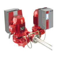
Design Envelope 4322 & 4372
Tango Pumping Unit
10
2.0 electrical setup
2.1 precautions
Safety, risk of death
All electrical connections should be carried out by
a qualified and authorised electrician in accordance
with local site regulations and the latest issue of the iee
regulations.
For retrofit applications with multiple pumping units
operating in parallel, the ampacity of conductors, ratings
of switches, branch-circuit, short circuit and ground-fault
protection should be reviewed prior to installation
(Reference nec/nfpa 70 section 430, or oesc section 28).
Before removing the main cover, the system must be
disconnected from the mains supply. After switching o,
wait for at least 4 minutes for the capacitors to
discharge before opening the cover.
Note, all drives have stored charge and all motors will
generate some amount of voltage to keep the drive
charged while spinning. If power is removed for more than
5 minutes and pump is still spinning, the check valve on
the outlet of the pump may be defective, allowing the
pump to spin backwards and continue to generate
voltage.
caution
High voltage testing (Megging) of the motor/inverter
may cause damage to the electronic components and
therefore should not be carried out.
2.1.1 ground leakage current
Ground leakage current is primarily caused by the
capacitance between motor phases and the motor
frame. The Radio Frequency Interference (rfi) filter
contributes additional leakage current, as the filter circuit is
connected to ground through capacitors.
The size of the leakage current to the ground depends on the
following factors, in order of priority:
1 Switching frequency
2 Motor grounded on site or not
The leakage current is of importance to safety during handling/
operation of the Design Envelope pump if (by mistake) the on-
board inverter has not been grounded.
Since the leakage current is >3.5mA (approx. 4-20mA),
reinforced Grounding must be established which is
required if en 50178 is to be complied with. Never use
elcb relays that are not suitable for dc fault currents (type A).
If elcb relays are used, they must be:
• Suitable for protecting equipment with a direct current con-
tent (dc) in the fault current (three-phase bridge rectifier)
• Suitable for power-up with short charging current to Ground
• Suitable for a high leakage current
2.1.2 start/stop of pump
The number of starts/stops via the mains voltage must not
exceed one-time per minute.
If a higher number of starts/stops is required, then the start/
stop digital input must be used (mains voltage directly con-
nected). This is the preferred method of starting and stopping
Design Envelope Pumps.
The three phase mains must be isolated before performing
maintenance of the pump.
2.1.3 additional motor protection
With the exception of supply fuses / MCB’s to protect
the installation (for over-current and short-circuit
protection), no additional overload or over-temperature
protection is required (i.e. thermal overloads).
Protection features include:
• Mains phase loss
• Over voltage
• Under voltage
• Electronic thermal motor protection
• Short circuit on motor terminals
• Ground fault on motor terminals
• Over temperature
2.1.4 motor thermal protection and derating
The Design Envelope motors are thermally protected in case
limits are exceeded, and additional protection is provided
through the drive.


 To Next Page