installation &
operating instructions
Design Envelope 4322 & 4372
Tango Pumping Unit
5
order and that all components are received as called for on the
packing list. Any shortages or damage should be reported im-
mediately. Use extreme care in handling the unit, placing slings
and hooks carefully so that stress will not be imposed on the
integrated controls, pump or motor. Never place cable slings
around the pump shaft or integrated controls. The hoist rings
should be used to lift the complete pump assembly.
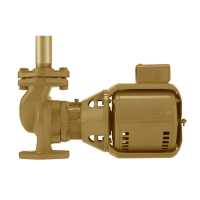
1.1.7 handling design envelope 4322 & 4372
units
To handle Design Envelope 4322 & 4372 units when received
on site, secure the pallet following uncovering the unit, then hook
straps as detailed below, and carefully lift the pumping unit to
stand the pump vertically upright. Lift only suciently to remove
the pallet, then lower onto a flat surface.
The pump and motor unit will free-stand on the casing ribs. Extra
care is required to ensure the integrated controls do not get
damaged during lifting and installation. Simply connect the lifting
straps to the lifting rings on each side of the unit.
As the lifting device is engaged (Using a spacer bar if necessary)
and the straps tighten ensure no part of the strapping is touching
any part of the control or motor fan cover. Lift the pumping unit
carefully from the pallet in this manner and allow the unit to stand
upright on a flat surface and re-position the straps, if necessary,
to ensure safe and damage-free transportation into the pipe
installation.
fig. 1.1.1
important:
Do not run the pump for any length of time under very
low flow conditions at the maximum speed or with the
discharge valve closed.
To do so could cause the water in the casing to reach super
heated steam conditions and will cause premature failure and
could cause serious and dramatic damage to the pump and
surrounding area.
1.2 mechanical installation
1.2.1 location
In open systems, locate the unit as close as practical to the
liquid being pumped, with a short, direct suction pipe. Ensure
adequate space is left above and around the unit for operation,
maintenance, service and inspection of parts.
In closed systems, where possible, the pumps should be installed
immediately downstream of the expansion tank /make-up con-
nection. This is the point of zero pressure change and is neces-
sary for eective pump operation. Do not install more than one
expansion tank connection into any closed hydronic system.
Electric motor driven pumps should not be located in damp or
dusty locations without special protection.
Airflow into the motor and/or motor fan should not be obstructed.
1.2.2 installation
When installing Vertical In-Line pumps, an important consid-
eration to accrue full added-value from the pump design is to
ensure that the pump is pipe-mounted and free to float with any
movement, expansion and contraction of the piping. If a Vertical
In-Line pump uses supports that rest on the base structure, it is
imperative that no pipe strain is imposed on the pump flanges.
Tell-tale pieces of equipment such as springs or wae style
neoprene isolation pads that distort with pressure to indicate
added piping weight, should be used under pump supports
should the pump not be truly pipe mounted.
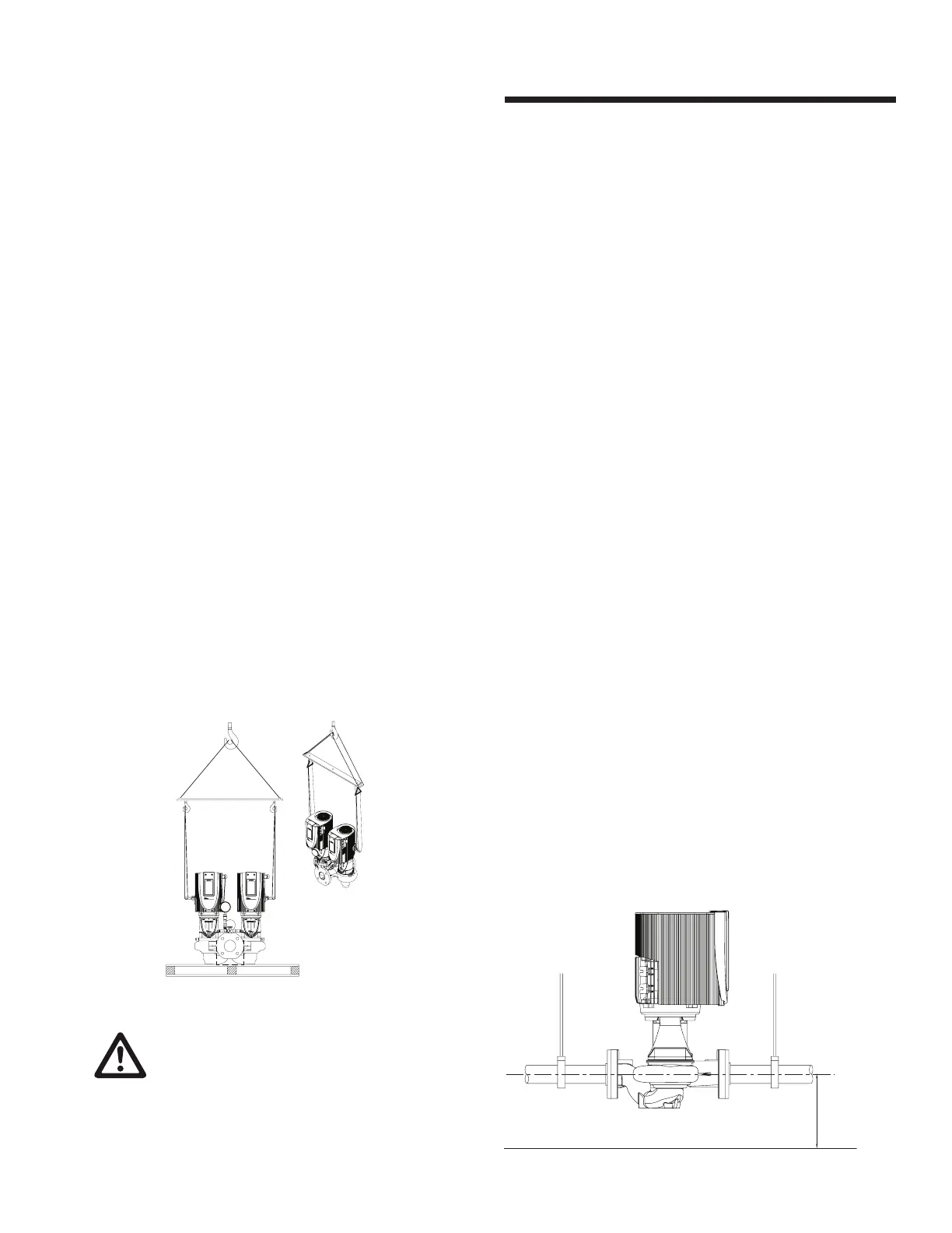
a hanger supported pipe mounted
4322 & 4372 Vertical In-Line pumps may be installed directly
in the system piping with no additional support. Pipe hangers
are simply sized for the additional weight of the pumping unit.
Many pumps are installed in this manner and can be mounted
at sucient height to take zero floor space
fig. 1.2.1
2' or 3'
height
above
finished
floor
For application with no suction guide, straight pipe of a length equivalent up to 4 times its
diamater for 1.5-6" pumps and 6 times diamater for 8" to 12" pumps will be required.
 Loading...