installation &
operating instructions
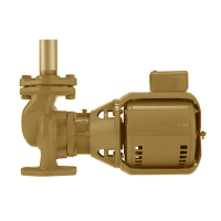
Design Envelope 4322 & 4372
Tango Pumping Unit
33
4.0 operation
4.1 start-up checklist
Particular care must be taken to check the following
before the pump is put into operation:
a Pump primed?
b Rotation ok?
c Lubrication ok?
d Pipe work properly supported?
e Voltage supply ok?
f Overload protection ok?
g Is the system clean?
h Is the area around the pump clean?
note: for depm2 motors:
Ensure that the STO jumpers are in place
Warranty
Does not cover any damages to the equipment resulting from
failure to observe the above precautions. Refer to Armstrong
General Terms and Warranty sheet. Contact your local Arm-
strong representative for full information.
4.2 starting pump
Ensure that the pump turns freely by hand, or with
some gentle mechanical help such as a strap or Allen
key in coupling bolt.
Ensure that all protective guarding is securely fixed in position.
The pump must be fully primed on start up. Fill the pump cas-
ing with liquid and rotate the shaft by hand to remove any air
trapped in the impeller. On split-coupled Design Envelope units
any air trapped in the casing as the system is filled must be
removed by the manual air vent in the seal flush line. Ensure
entrained air is removed from Design Envelope pumps, prior to
starting, through the air vent on the seal flush line. Open vent
until clear of air.
Design Envelope close-coupled units are fitted with seal flush/
vent lines piped to the pump suction area. When these units op-
erate, residual air is drawn out of the pump towards the suction
piping. energize the motor momentarily and check that the rota-
tion corresponds with the directional arrow on the pump casing
(clockwise when viewed from non-drive end of motor).
Start the pump with the discharge valve closed and the suction
valve open, then gradually open the discharge valve when the
motor is at operating speed. The discharge valve may be cracked
or open slightly at start up to help eliminate trapped air.
When stopping the pump: Close the discharge valve and
de-energize the motor.
Do not run the pump against a closed discharge valve at full speed
for an extended period of time (a few minutes maximum.)
Should the pump be noisy or vibrate on start-up a common
reason is overstated system head. Check this by calculating the
pump operating head by deducting the suction pressure gauge
value from the discharge gauge reading. Convert the result into
the units of the pump head as stated on the pump nameplate
and compare the values. The system designer or operator
should be made aware of this soon as some adjustment may be
required to the drive settings to make the pump suitable for the
system as installed.
Check that each motor rotation corresponds to the
casing flow directional arrow markings.
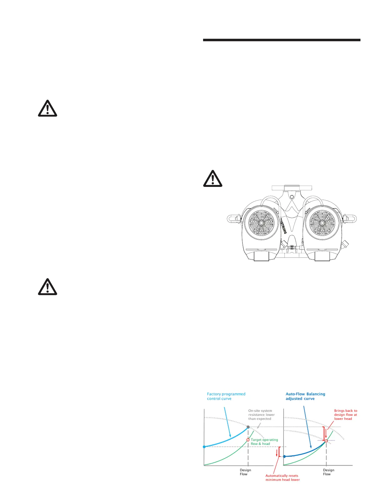
4.2.1 auto flow balancing
Auto-Flow Balancing automatically determines the control
curve between the design flow at the on-site system head,
and the minimum (zero-flow) head that will typically be
lowered (reset).
Often the actual system head is less than expected, and the
pump will operate further to the right of the curve at a higher
flow rate than it was designed for due to less system resistance.
The Auto Flow Balancing function performs a scan of the
sensorless map against the actual system to establish the actual
head for the design flow. The minimum (zero-flow) head will
be reset according to the actual head at the design flow – the
factory default is 40% of the design head, but can be lowered
further for more energy savings if all zones are still satisfied.
 Loading...