installation &
operating instructions
Design Envelope 4322 & 4372
Tango Pumping Unit
49
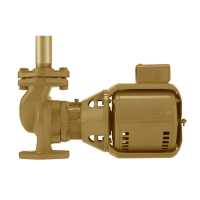
For 2 pump parallel operation:
Ensure that both terminating resistor switches are set to En-
abled (towards the en label for the canbus port).
g
g
A = + Positive
B = - Negative
G = Ground
A = + Positive
B = - Negative
G = Ground
For 3 or 4 pump parallel operation:
Ensure that only the first and last terminating resistor switches
are set to Enabled (towards the en label for the canbus port).
g
g
A = + Positive
B = - Negative
G = Ground
A = + Positive
B = - Negative
G = Ground
g
A = + Positive
B = - Negative
G = Ground
g
g
A = + Positive
B = - Negative
G = Ground
A = + Positive
B = - Negative
G = Ground
g
A = + Positive
B = - Negative
G = Ground
g
A = + Positive
B = - Negative
G = Ground
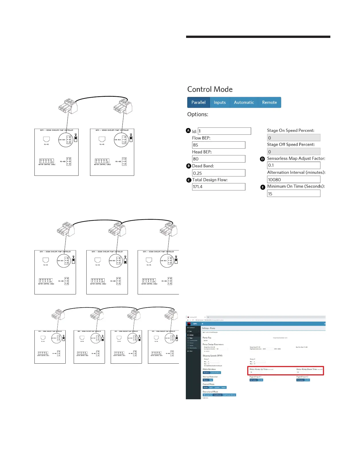
From the Webserver, choose Settings -> Pump, set control
mode to Parallel with the following parameter values:
A id: 1 to 8, the lower number is the lead pump
e.g. enter 1 for lead pump, 2 for lag pump
B Dead Band: set to 0.25
C Total Design Flow: enter the parallel flow rate
D Sensorless Map Adjust Factor: set to 0.1
e Minimum On Time (seconds): set to 15
Click update to save all changes. Connect the Webserver to
the second pump and then repeat above steps A to e.
5.8.2 modifying motor ramp up and down time
Modify the time in the respective fields after clicking on Pump
under Settings
 Loading...