installation &
operating instructions
Design Envelope 4322 & 4372
Tango Pumping Unit
8
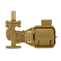
j horizontal shaft mounting
Design Envelope pump units with Permanent Magnet motors
can be installed in a horizontal shaft orientation
fig. 1.2.10
k The motor and integrated control assembly has one fac-
tory orientations - facing the discharge.
If not convenient for other equipment, motor and controls
may be rotated at installation site at 90˚ increments and
the rotating assembly at up to 45˚ in either direction, pro-
vided there are no physical clashes with other equipment.
Remove the clamp ring between the casing and adaptor/
pedestal and carefully rotate the rotating assembly. Note
that the seal flush line may need to be replaced to fit the
new orientation.
fig. 1.2.11
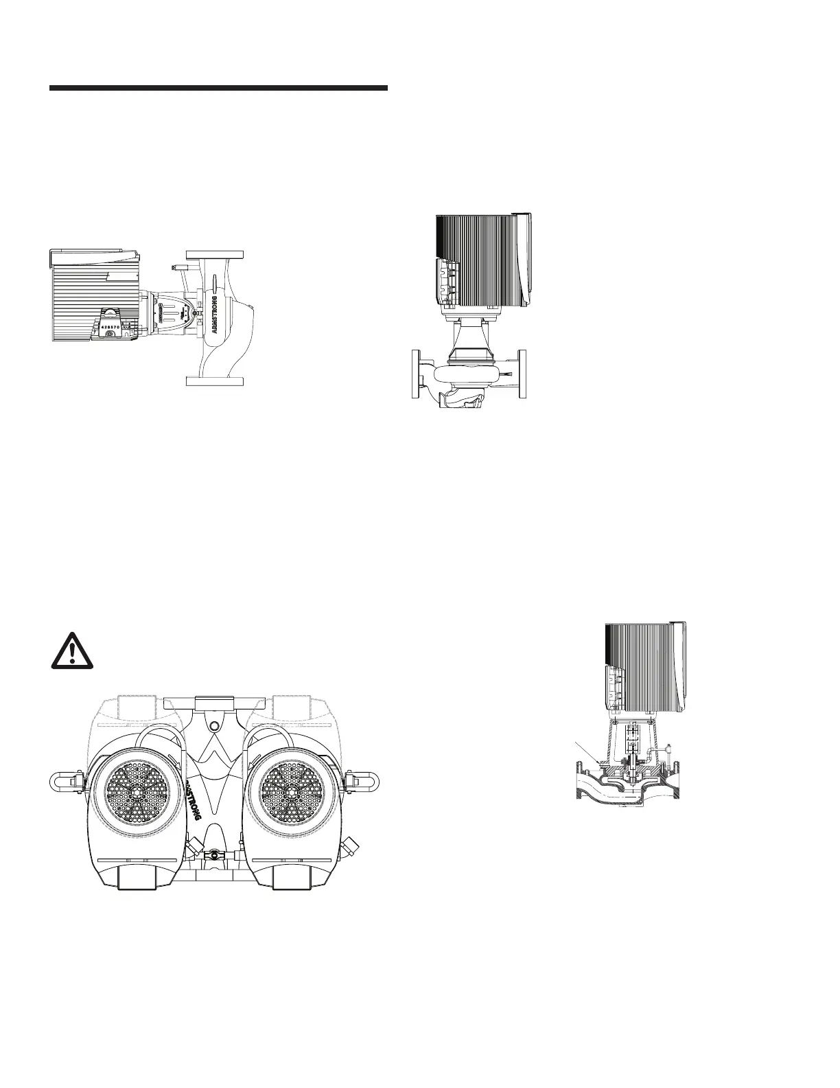
l clearance note
fig . 1.2.12
important:
All split-coupled Design Envelope pumps contain a tapped
hole in the motor bracket above the discharge flange (see fig.
1.2.13) for draining the well. Pipe this drain hole to a floor drain
to avoid overflow of the cavity caused by collecting chilled wa-
ter condensate or from seal failure.
m tapped collection well on design envelope 4322
fig. 1.2.13
Seal leaks or condensate
drain hole. Plumb to drain for
area cleanliness.
The working clearance in front of
the controls should be sucient for
access to service the controls
When reinstalling the clamp, tighten the clamp nut to
90-100 in-lb torque.
 Loading...