MAX1000 User Guide www.arrow.com
Page | 10 July 2017
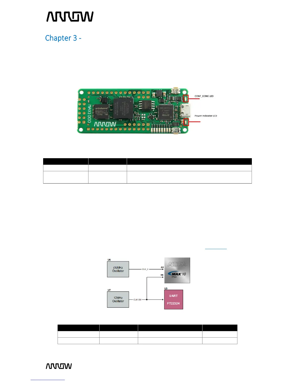
Connections and Peripherals of the MAX1000 Board
3.1 Board Status Elements
In addition to the 8 LEDs that the FPGA can control, there are 2 additional LEDs which can indicate
the status of the board.
On when 3.3V power is active
On when configuration data was loaded to MAX10 device
without error
3.2 Clock Circuitry
All the external clocks of the system can be seen in Figure 4. The default clock (CLK12M) is at
12 MHz and is connected and driving the FPGA’s user logic and the Arrow USB Programmer2.
There is an optional slot of another clock (CLK_X) to add another preferred clock source to the
FPGA. Both clocks are driving PLL1/PLL3, which are able to drive the ADC clock.
For more information on clocks and PLLs of the MAX10, please refer to this document.
Figure 3 – Position of Indication LEDs
Figure 4 – MAX1000 Clock Tree