MAX1000 User Guide www.arrow.com
Page | 13 July 2017
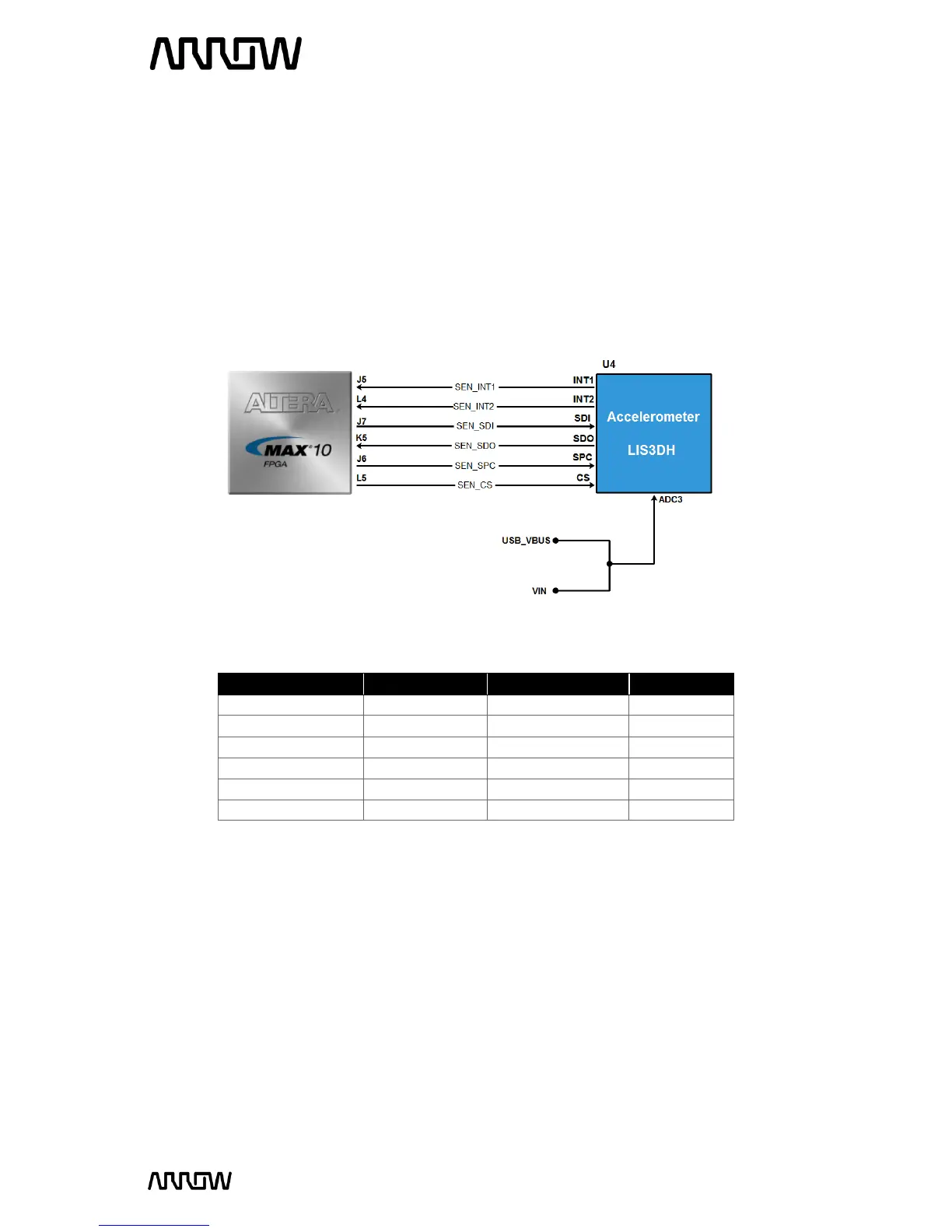
3.3.3 Accelerometer
The board comes with a digital accelerometer (LIS3DH), commonly known as the G-Sensor. This
G-Sensor is a small, thin, ultra-low power consumption, 3-axis accelerometer with digital I2C/SPI
serial interface, standard output. The LIS3DH has user-selectable full scales of +/-2g, +/-4g, +/-8g,
+/-16g and it is capable of measuring accelerations with output data rates from 1 Hz to 5 kHz. The
supplied power to the board (coming either from micro-USB connection or user Vin) can be
monitored through the ADC channel 3 of the accelerometer.