EasyManua.ls Logo

Arrow MAX1000 - Figure 15 - JTAG Connections

Arrow MAX1000
74 pages
Print Icon
To Next Page IconTo Next Page
To Previous Page IconTo Previous Page
Loading...
MAX1000 User Guide www.arrow.com
Page | 20 July 2017
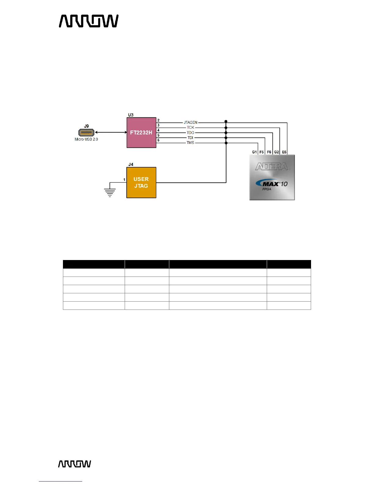
The FPGA device can be configured through JTAG interface on MAX1000, but the JTAG chain must
form a closed loop, which allows Quartus Prime programmer to detect the FPGA device.
MAX1000 offers two ways of configuring your board.
1) Through the on-board Arrow USB Programmer2
2) Pins for connecting user’s preferred JTAG interface
Board Reference
FPGA Pin No.
Description
I/O Standard
JTAGEN
PIN_E5
Dual Function: JTAG Pin Sharing
3.3 V
TCK
PIN_G2
Test Interface Clock
3.3 V
TDO
PIN_F6
Test Data Out
3.3 V
TDI
PIN_F5
Test Data In
3.3 V
TMS
PIN_G1
Test Mode Select
3.3 V
For detailed information about how to configure the MAX10 device, please refer to Chapter 6.
Figure 15 JTAG Connections

Table of Contents

Related product manuals