MAX1000 User Guide www.arrow.com
Page | 16 July 2017
3.3.6 User I/O
The MAX1000 board has two pins that can be connected to the board and take analogue inputs.
Those two pins are connected to the ADC block of the MAX10 and can measure up to 3.6V. This
12-bit SAR ADC can reach 1 MSPS and has single ended capabilities.
For more information on the ADCs of the MAX10, please refer to this document.
Note: If you use bank 1A for ADC, you cannot use the bank for GPIO.
Dedicated analogue input pin
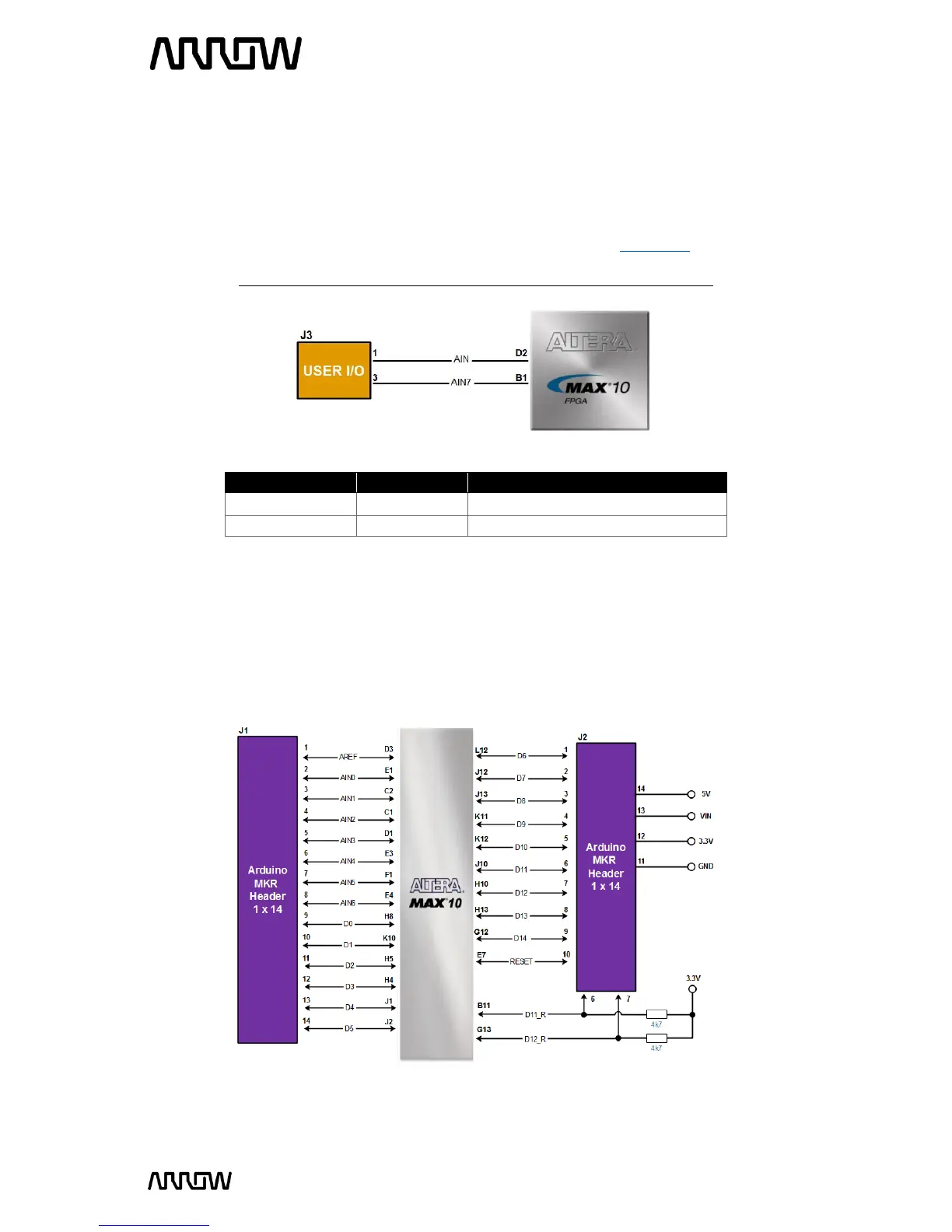
3.3.7 Arduino MKR Connectors
The MAX1000 board offers connectivity to Arduino MKR compatible shields that could also
alternatively be used as GPIOs. The MKR connectors offer up to 7 analogue inputs and 15 digital
I/Os. There is also an option to use or not use the 4.7k Ohm pull-up resistor lines for
communication interfaces.
Figure 11 - User I/O Connections
Figure 12 - Arduino MKR Header Connections