ITS101 Installation Manual
The pin-out of the 3-pin Power connector (J11) is given in next table.
Pin (left to right) Name PCB Signal
1 + +10 .. +14 V DC
2 - GND
3 Chassis_GND (EARTH)
Table 1: Power connector.
2.2. RELAY
The ITS101 has two small signal relay outputs. These relays are not meant for direct
switching of 110 or 220 V AC applications or high currents. They can be used to signal
the control-unit of a barrier or an outdoor 24 V DC signal-LED.
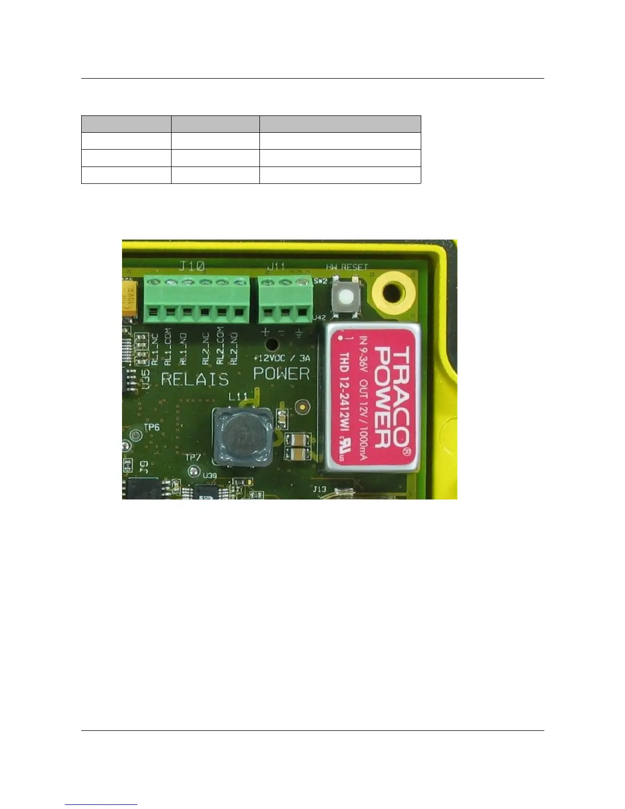
The pin-out of the 6-pin Relay connector (J10) is given in next table. See Figure 2 for a
detailed PCB picture of this relay connector (name on the PCB rev. A is by mistake RELAIS).
ARVOO Imaging Products B.V. page 6 of 33
Figure 2: Detail of the POWER and RELAY connectors. Also the
hardware reset switch is visible at the upper-right corner.