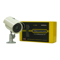
ITS101 Installation Manual
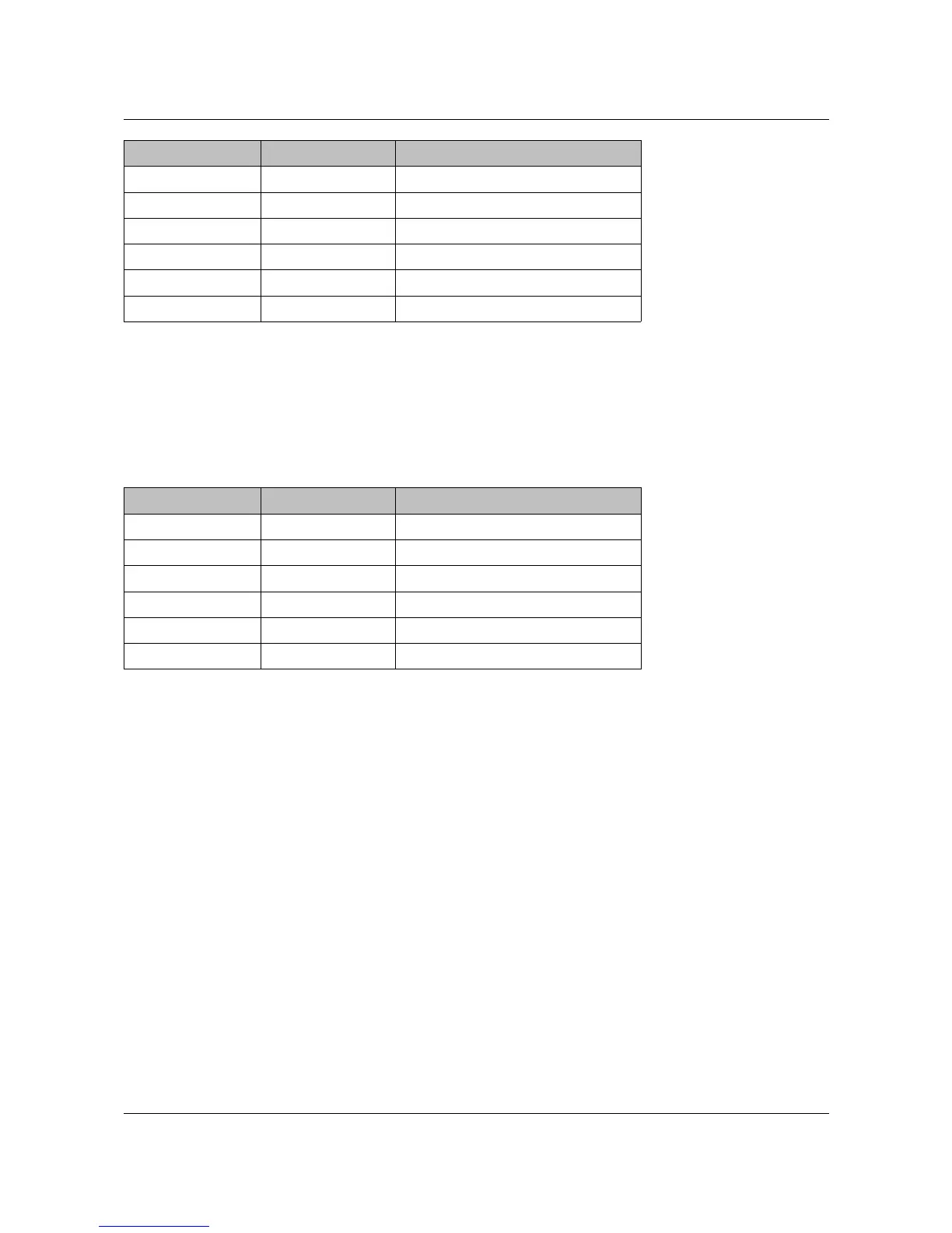
Pin (left to right) Name PCB Signal
1 RL1_NC Relay 1, Normally Closed
2 RL1_COM Relay 1, Common
3 RL1_NO Relay 1, Normally Open
4 RL2_NC Relay 2, Normally Closed
5 RL2_COM Relay 2, Common
6 RL2_NO Relay 2, Normally Open
Table 2: Relay connector pin-out.
2.3. RS-232
An RS-232 port is optionally in use by the ANPR application. We refer to documentation of the
ANPR application.
The pin-out of the 6-pin RS-232 connector (J6) is given in next table.
Pin (left to right) Name PCB Signal
1 TX1 Transmit port 1
2 RX1 Receive port 1
3 GND GND
4 TX2 Transmit port 2
5 RX2 Receive port 2
6 GND GND
Table 3: RS-232 connector pin-out.
ARVOO Imaging Products B.V. page 7 of 33