ITS101 Installation Manual
2.4. GPIO
For detailed input and output specifications, see Chapter 6 Technical specifications.
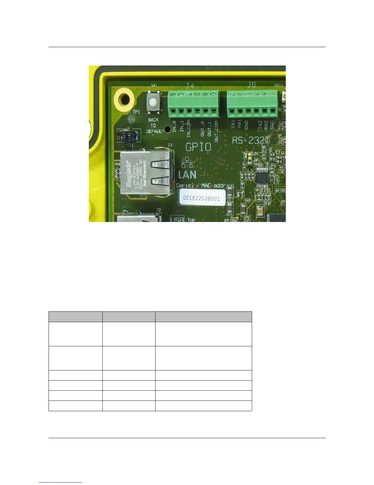
The pin-out of the 6-pin GPIO connector (J4) is given in next table. See Figure 3 for a detailed
PCB picture of this GPIO connector.
Pin (left to right) Name PCB Signal
1 IN_0 Input 1. Slow input signals can
be seen on front by means of
LED-indication. Range: 5-12 V.
2 IN_1 Input 2. Slow input signals can
be seen on front by means of
LED-indication. Range: 5-12 V.
3 IN_COM Common for the inputs.
4 OUT_0 Output 1.
5 OUT_1 Output 2.
6 OUT_COM Common for the outputs.
Table 4: GPIO connector pin-out.
ARVOO Imaging Products B.V. page 8 of 33
Figure 3: Detail RS-232, GPIO and LAN connectors.