Ascon Tecnologic - X34 - OPERATING INSTRUCTIONS - PAG. 11
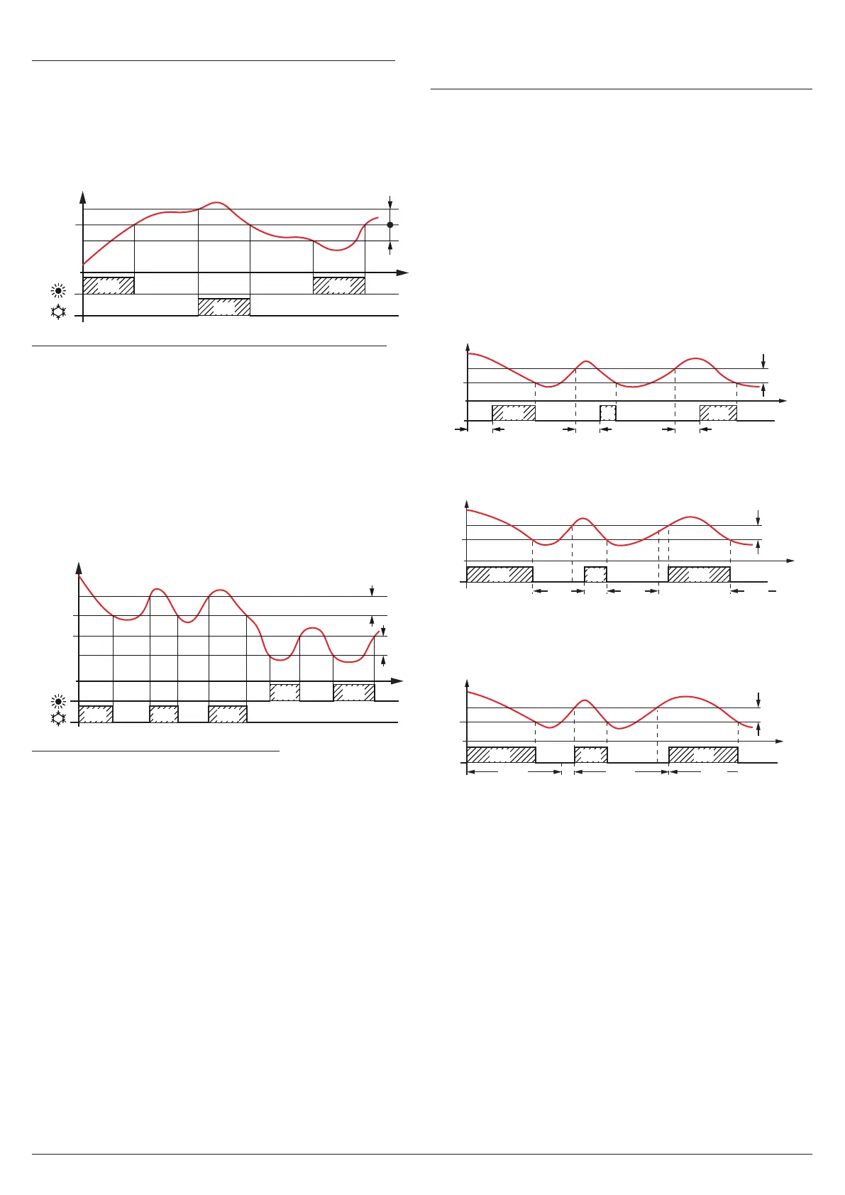
nr Neutral Zone or Cooling and Heating a single Set Point
When r.HC = nr, the output configured as ot operates with a
Cooling action (like r.HC = C) while the output configured as
HE operates with a heating action; both the actions use the
active Set Point (SP/SPE/SPH). The intervention differential
(r.d/r.Ed/r.Hd) is automatically assumed by the controller
to have positive values for the Cooling action and negative
values for the Heating action.
SP
off off
ON
Temp.
time
r.d
r.d
offoff
r.Hc
ON
ON
HE
ot
Outputs
Pr1
HC Cooling and Heating with two independent set points
As in the previous case, when r.HC = HC the output config-
ured as ot operates with Cooling action (like r.HC = C) while
the output configured as HE operates with Heating action. In
this case, however, the Set Point for the ot output is the ac-
tive one (SP/SPE/SPH) while for HE output the Set Point is
SPH. The intervention differential for the ot output is the ac-
tive differential (r.d/r.Ed/r.Hd) and is automatically assumed
by the controller to have positive values for the Cooling ac-
tion while for the output HE the differential is r.Hd considered
with negative values as for the Heating actions.
In this mode, the activation of the Turbo cycle causes the
instrument to operate with Neutral Zone and SPH set point.
SP
SPH
off off off
Temp.
time
r.d
r.Hd
offoff
off
R.HC = HC
ON ON ON
ONON
HE
ot
Pr1
Outputs
C3 Cooling with three automatic modes
The instrument still operates with Cooling action, but this
selection activates automatic switching between the three
modes: Normal, Eco and Turbo as already described in the
section on operating modes.
The time protections described in the next paragraph (PP1/
PP2/PP3) always work on the output configured as ot.
In the event of a probe error, it is possible to set the instru-
ment so that the ot output continues working in cycles accord-
ing to the times programmed with parameters r.t1 (activation
time) and r.t2 (deactivation time). If a Pr1 probe error occurs,
the instrument continues activating ot output for r.t1 time then
disabling it for r.t2 time and so on until the error persists.
By programming r.t1 = oF the ot output in probe error con-
dition remains OFF. On the other hand, programming r.t1 to
any value and r.t2 = oF the ot output, in probe error condi-
tion, remains always ON.
Remember that the operation of the temperature controller
can be conditioned by the following functions: Compressor
protection function and power-ON delay, Defrost, Open door
and External alarm with output disable.
5.7 Compressor protection function and
power-ON delay
All parameters concerning the compressor protection func-
tions can be found in the ]pr group.
The “Compressor Protection” function aims to avoid repeated
compressor start-ups controlled by the instrument in Cooling
applications or otherwise can be used to add a timed control
on the actuator control output.
This function foresees 3 time controls on the switching ON
of the output configured as ot associated to the temperature
control request. The protection consists in preventing the ot
output being switched ON during the times set with param-
eters P.P1, P.P2 and P.P3 and therefore that any activation
occurs only upon expiry of all protection times.
1. First control (parameter P.P1) foresees a delay to ot out-
put activation (switching-ON delay).
SP
time
offoff off off
ON
ON
r.d
P.P1
P.P1
ot
ON
Pr1
Output
P.P1 P.P1
2. Second control (parameter P.P2) foresees an inhibition to
the activation of the output by a time delay that starts when
the output is turned OFF (delay after switching-OFF).
offoff off
ON
SP
time
r.d
P.P2
ON ON
Temp.
ot
Pr1
Output
P.P2 P.P2 P.P2
3. Third control (parameter P.P3) foresees an inhibition to the
activation of the output by a time delay that starts when
the output was turned ON last time (delay between two
switching-ON).
offoffoff
ON
SP
time
r.d
P.P3
P.P3 P.P3
P.P3
ON ON
Temp.
ot
Pr1
Output
During the output inhibition the led OUT (Cool or Heat) blinks.
It is also possible to prevent the activation of all the outputs
after the instrument is turned ON for the time set at param-
eter P.od (Power ON delay).
During the power ON delay phase, the display shows the
indication od, alternated with the normal display.
These functions are disabled when all the relative param-
eters are set to oF (P.P1, P.P2, P.P3 and P.od = oF).
In case HOT-GAS defrost mode for centralized systems
(d.dt = HG), the parameters P.P1 and P.P2 are used to set
the activation delay of the Liquid solenoid valve and the de-
activation delay of the Aspiration solenoid valve (see “H OT-
GAS defrost operation for centralized systems”).