Ascon Tecnologic - X34 - OPERATING INSTRUCTIONS - PAG. 2
1. INSTRUMENT DESCRIPTION
1.1 General description
The X34 model is a digital electronic microprocessor control-
ler that can be used typically for refrigeration applications.
It has ON/OFF temperature control and defrost control at
defined times (Real Time Clock Defrosting), at time intervals,
by arrival at temperature or by length of time of continuous
compressor operation through stopping the compressor,
electric heating or hot gas/cycle inversion; moreover, it can
also be used in systems with refrigeration units equipped
with hot gas defrost. The appliance has special defrosting
optimization functions and other special tasks to reduce the
amount of energy used by the controlled system.
The instrument has up to 4 relay outputs, up to 4 inputs
configurable for PTC, NTC and Pt1000 temperature probes,
and 2 digital inputs. It can be also equipped with an in-
ternal buzzer for acoustic notification of alarms, an RS485
serial communication interface with MODBUS-RTU com-
munication protocol and a calendar clock.
The calendar clock allows to program defrosting events, auxiliary
output switching, control Set Point changes, instrument ON/OFF,
etc. at pre-set times (max. 14 daily and 98 weekly events).
A furher feature of the calendar clock instrument version is
the HACCP function which can store the last 10 occurred
alarms (alarm type, start, duration and temperature peaks).
The 4 outputs can be used to control the compressor or
the temperature control device, the defroster, the evapora-
tor fans and a configurable auxiliary device (Light, Alarm,
second evaporator, etc.).
The 4 temperature probe inputs can be used to control
the cell temperature, to measure the evaporator temperature
and othe two auxiliary temperatures (e.g.: product tem-
perature, condenser temperature, temperature of a sEcond
evaporator, etc.).
Two digital inputs are always available and, as an alterna-
tive to the Pr3 and Pr4 temperature probe inputs, two other
digital inputs can be configured.
The 2... 4 digital inputs can be configured to execute various
functions such as cell door signal, defrost commands, select-
ing a different temperature-control Set Point, reporting an
external alarm, activating a continuous cycle, activating the
auxiliary output, etc..
The model X34S have the “S-touch” capacitive sensor key-
board system.
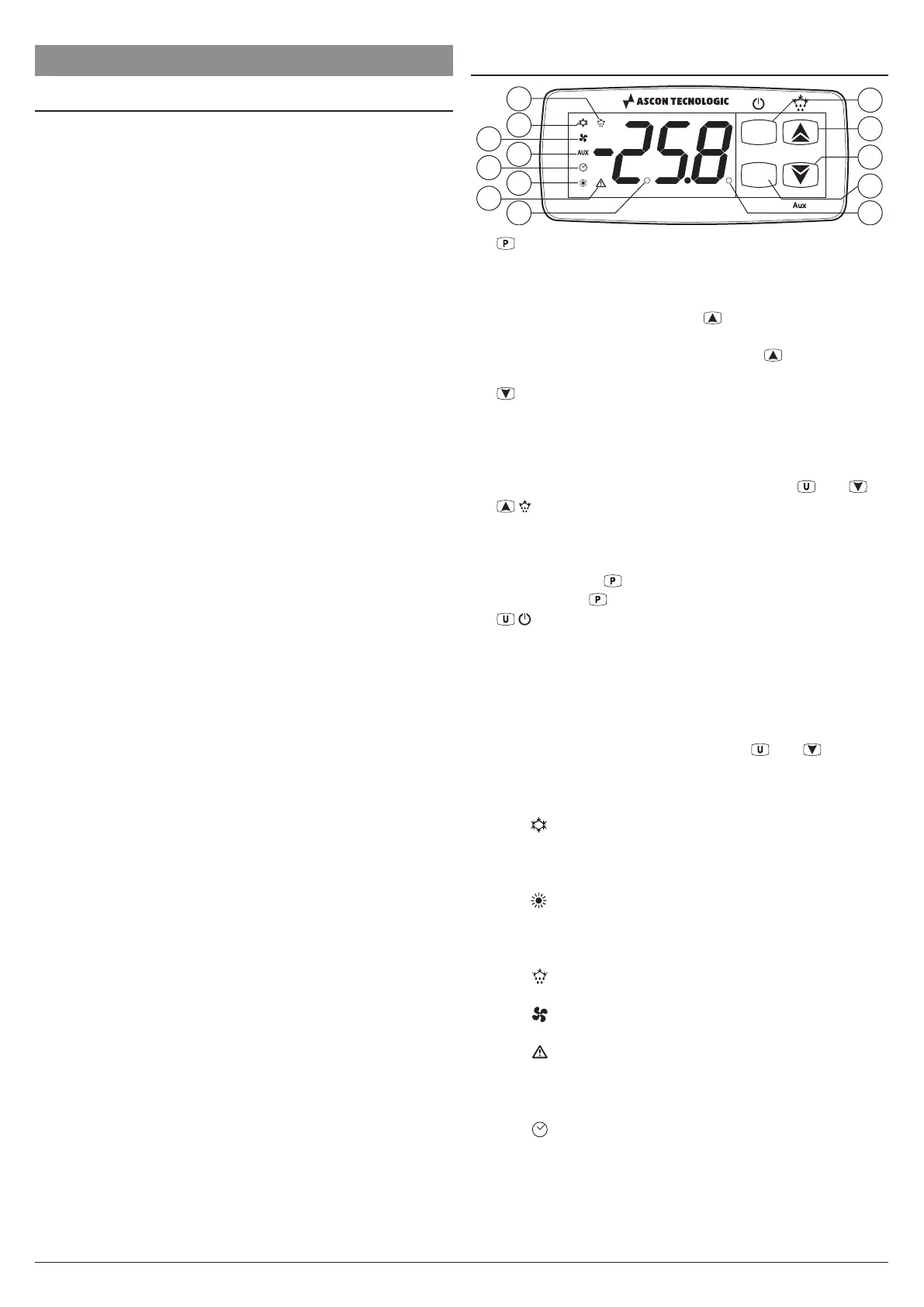
1.2 Front panel description
P
U
X34
1
5
3
2
4
10
9
12
7
13
6
11
8
1. Key:
Used to set the Set Point (press and release) and
to program the function parameters (pressed for 5 s).
In programming mode is used to enter at parameters edit
mode and confirm the values. In programming mode it
can be used together with the
key to change the pro-
gramming level of the parameters. When the keyboard is
locked it can be used together with the
(hold pressed
for 5 s) key to unlock the keyboard.
2. /Aux Key: In programming mode is used for decreas-
ing the values to be set and for selecting the parameters.
Hold pressed for 1 s, while in Normal mode, it can also be
programmed via parameter t.Fb to carry out other func-
tions such as activating the Aux output, starting up the
continuous cycle, etc. (see functions of keys and ).
3.
/
Key: In Normal mode can be used to start/stop a
manual defrost (pressed for 5 s). In programming mode
is used to increase the value to be set and to select the
parameters. In programming mode can be used, to-
gether with key
to change parameters level. Pressed
together with
key for 5 s allows the keyboard unlock.
4. /
Key: Press and release the key to display the
instrument variables (measured temperatures etc.). In
programming mode press the key for 2 s to return in Nor-
mal mode. Hold pressed for 1 s, while in Normal mode,
it can also be programmed via parameter tuF to carry
out other functions such as turn ON and OFF (stand-by)
the device, activate the Aux output, start up the continu-
ous cycle, etc. (see functions of keys and ).
5. LED SET: During the normal operating mode, signals
that a ket is pressed. In programming mode indicates
the programming level of the parameters.
6. LED - COOL:
Indicates the output status (compres-
sor or temperature control device) when the istrument is
programmed for cooling operation: on (on), off (off) or
inhibited (flashing).
7. LED - HEAT:
Indicates the output status (compres-
sor or temperature control device) when the istrument is
programmed for heating operation: on (on), off (off) or
inhibited (flashing).
8. LED
: Indicates: Defrost in progress (on) or drainage
time in progress (flashing).
9. LED
: Shows the Fan output status: on (on), off (off) or
inhibited (flashing).
10. LED
: Shows the Alarm status (on), off (off) and Ac-
knowledged or Lached (flashing)
11. LED Aux: Shows the Auxiliary output status: on (on), off
(off) or inhibited (flashing).
12. LED
: Indicates that the internal clock is running. If
flashing slowly, it means that there is a clock error (clock
chip not working). If flashing rapidly, it means the clock
battery is drained
13. LED Stand-By: When the instrument is in Stand-by
mode is the only lit LED.