Ascon Tecnologic - X34 - OPERATING INSTRUCTIONS - PAG. 16
always be switched ON independently of the defrost status
(F.FE = on) or switched OFF during defrost (F.FE = oF); in
this later case, it is possible to delay the fans re-start even
after the end of the defrost by the time set at parameterF.Fd.
When this delay is active the
LED
flashes to signal the
delay in progress.
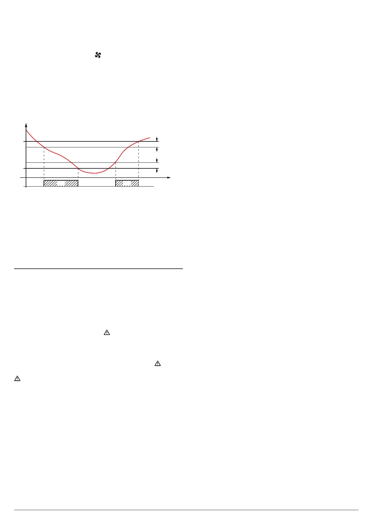
When the evaporator probe is used the fans, as well as be-
ing conditioned by the parameters F.tn, F.tn and F.FE, are
also conditioned by a temperature control.
In fact it is possible disable the fans when the temperature
measured by EP evaporator probe is higher than the one set
at parameter F.FL (temperature too hot) or lower than the
one set at parameter F.LF (temperature too cold).
Fn
F.LF
Ep
F.FL
F.dF
F.dF
time
offoff offON ON
Note: Particular attention should be paid to the proper use of
fan-based temperature control functions, as in a typi-
cal refrigeration application, the evaporator fan stop
blocks the heat exchange.
The relative differential that can be set at parameter F.dF is
also associated with these parameters.
Remember that the fans functioning can be conditioned by
the “Door open” function controlled by digital input.
5.10 Alarm functions
All parameters concerning the Alarm functions are contained
in the group ]Al.
The alarm conditions of the instrument are:
– Probe errors: E1, -E1, E2, -E2, E3, -E3, E4, -E4;
– Temperature alarms: H1, L1, H2, L2;
– External alarm: AL, PrA, HP, LP;
– Open door alarm: oP;
The alarm functions act on LED
, on the internal buzzer
(when present and configured with parameter o.bu) and on
the output selected with parameters o.o1, o.o2, o.o3 and o.o4
according to the parameters set.
All alarm conditions are pointed out lighting up the
LED,
while the acknowledged alarm is indicated by the flashing of
LED.
The buzzer (when present) can be programmed to be
activated when an alarm occurs (o.bu = 1 or 3) and can be
disabled (alarm silencing) manually by pressing any of the
instrument keys.
The possible selections of output parameters for the alarm
signalling function are:
At
When the output is to be activated in alarm condition and
can be deactivated manually by pressing any key of the
instrument (typical application for an acoustic signal);
AL When the output is to be activated in alarm condition but
cannot be deactivated manually; it is then deactivated
only when the alarm status ceases (typical application
for a light signal);
an When the output is to be activated in alarm condition
and must remain active even when the alarm status has
ceased. The disabling action (recognition of a stored
alarm) can only be carried out manually by pressing any
key when the alarm status has removed (typical applica-
tion for light signal).
-t Function similar to At but with inverse logic function
(output active in normal conditions, disabled in alarm).
-L Function similar to AL but with inverse logic function
(output active in normal conditions, disabled in alarm).
-n Function is similar to An but with inverse logic function
(output active in normal conditions, disabled in alarm).
5.10.1 Temperature alarms
The instrument has 2 temperature alarms, fully configurable
with a maximum and a minimum threshold.
The temperature alarms work according to the probe measure-
ments set at parameters A.y1 and A.y2, the alarm thresholds
set with parameters A.H1 and A.H2(max. alarms) and A.L1 and
A.l2 (min. alarms) and the relative differentials A.d2 and A.d2.
Using parameters
A.y1
and
A.y2
it is also possible to define
whether the alarm thresholds
A.H1
,
A.H2
,
A.l1
,
A.l2
are abso-
lute or relative to the set point.
Depending on the desired alarm operating mode, parameter
A.y1 and A.y2
can be set as:
1
Absolute alarms referred to Pr1 and display of label (H - L);
2
Relative alarms referred to Pr1 and display of label (H - L);
3
Absolute alarms referred to Au and display of label (H - L);
4
Relative alarms referred to Au and display of label (H - L);
5
Absolute alarms referred to CD and display of label (H - L);
6 Absolute alarms referred to Pr1, no label displayed;
7 Relative alarms referred to Pr1, no label displayed;
8 Absolute alarms referred to Au, no label displayed;
9 Relative alarms referred to Au, no label displayed;
10 Absolute alarms referred to CD, no label displayed;
11
Absolute alarms referred to EP and display of label (H - L);
12 Absolute alarms referred to
EP
, no label displayed.
Using some parameters it is also possible to delay the enabling
and the intervention of these alarms. These parameters are:
A.P1, A.P2
Temperature alarm intervention delay at instrument
power ON when the instrument is in alarm status
at power ON. If the instrument is not in alarm sta-
tus at power ON, A.P1 and A.P2 are not considered.
A.da This is the time period during which temperature
alarms 1 are disabled at the end of a defrost cycle.
Note: During defrosts and after defrosts for the time set with
A.dA, alarm 1 is disabled, whereas during defrosts
alarm 2 is always enabled.
A.t1, A.t2
Activation delay times for temperature alarms 1 and 2.
Temperature alarms 1 and 2 are enabled at the end of the
alarm-disabling time periods and activated after time periods
A.t1 and A.t2 when the temperature measured by the probe
configured for the alarm rises above or drops below the
respective maximum and minimum alarm thresholds.
By means of parameters A.A1 and A.A2 it is also possible to
set the action of the alarms on the control output and on the
alarm outputs (buzzer included).
This means that, for example, is possible to intervene on the
control output directly, by deactivating it in the case there are
temperature alarms also on the probes configured as Au (e.g.
antifreeze function) or as CD (e.g. dirty condenser function).