Ascon Tecnologic - X34 - OPERATING INSTRUCTIONS - PAG. 15
same used to control the temperature) must also be closed
to isolate the evaporator.
Evaporator n
Liquid
(ot)
Fan (Fn)
Hot Gas (dF)
Suction (Au)
Suction (Au)
Evaporator 2
Liquid
(ot)
Fan (Fn)
Hot Gas (dF)
Suction (Au)
Evaporator 1
Liquid
(ot)
Fan (Fn)
Hot Gas (dF)
Suction line
Hot Gas line
Liquid line
Compressor Rack Unit
Note: For greater clarity in the diagram, some details con-
cerning the hydraulic circuit have been deliberately
omitted (non-return valves etc.) because they are not
controlled by the instrument but are still necessary for
the correct system operation.
To avoid sudden pressure changes in the plant, the defrost
phases are performed respecting a precise sequence de-
scribed below.
The system configured for the Hot Gas defrost in central-
ized plants behaves as follows:
– At start-up, the Suction solenoid valve is activated im-
mediately (if set, respecting the P.od delay), after which, if
there is a cooling request, also the Liquid solenoid valve is
activated (respecting the P.P1 delay).
– During the controller phase, the Suction solenoid valve is
therefore always activated while the Liquid valve is acti-
vated as a function of the temperature control.
r.d
Liquid
(ot)
SP
Temp.
time
P.P1
Pr1
Suction
(Au o.fo=3)
off
off
A) Defrosting occurs first of all with the immediate deactiva-
tion (if active) of the Liquid valve (ot output);
B) So, after the delay set at parameter P.P2 also deactivates
the Suction valve (output Au configured with o.Fo = 3)
and, if parameter F.FE = oF, the fan output is also deacti-
vated (output Fn);
Note: During this period of time, the fans operation and
maintaining the suction valve open are necessary to
facilitate the complete evaporation of the fluid con-
tained in the evaporator.
If the defrost request occurs when the Liquid valve outlet
is already closed and the time P.P2 has elapsed (which
counting always starts when the ot output is turned OFF)
the deactivation of the Suction valve and eventually of
the fans is immediate.
Otherwise, the defrost request happens during the P.P2 time
count, the Suction valve and the fans deactivation occurs at
the when P.P2 counting expires. At this point the Hot Gas
valve is activated (dF output) and the defrost begins;
C
At defrost end (always handled by the d.dE time or by the
evaporator temperature d.tE or by the manual control), the
output dF is deactivated and the delay times d.td (drip-
ping time) and F.Fd are activated (fans delay after defrost);
D When d.td time counting has elapsed, the output of the
Suction solenoid valve is reactivated, as when the instru-
ment is switched ON;
E In the event that, as often happens, the temperature
controller should request it, after the P.P1 time the Liquid
valve will be activated and the instrument returns to the
normal temperature control mode;
F When F.Fd time counting has elapsed, fans are re-acti-
vated if the evaporator temperature is lower than the one
set at parameter F.FL;
Fan
(Fn)
F.Fd
d.tdP.P2
Suction
(Au, o.fo=3)
off
Liquid
(ot)
off
Defrost
(dF)
offoff
off
AB CDEF
d.dE
P.P1
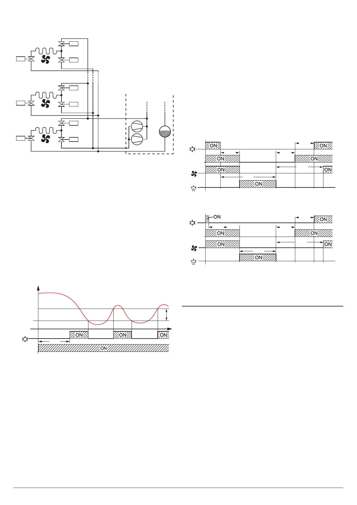
Example of Hot Gas defrost for centralized systems with
defrost start when the Liquid valve is open.
Fan
(Fn)
Suction
(Au, o.fo=3)
off
Liquid
(ot)
off
Defrost
(dF)
offoff
off
BCDEF
P.P1
d.tdP.P2
F.Fd
d.dE
Example of Hot Gas defrost for centralized systems with
defrost start when the Liquid valve is closed hafter the P.P2
time counting has expired.
5.9 Evaporator fans control
All parameters concerning evaporator fans control are con-
tained in the group ]Fn.
The fans control operates on the output configured as Fn
depending on certain instrument control statuses and the
temperature measured by the EP evaporator probe.
In the case that EP evaporator probe is not used or in error ,
the output Fn is activated only depending on the parameters
F.tn, F.tF and F.FE.
Parameters F.tn and F.tF decides the fans functioning when
the output configured as ot (compressor) is OFF.
When output ot is OFF , it is possible to set the instrument
so that that the Fn output continues working in cycles ac-
cording to the times programmed at the parameters F.tn (fan
activation time) and F.tF (fan deactivation time).
When ot output is switched OFF, the instrument activates the
Fn output for the time F.tn, then deactivates it for the time
F.tF and so on whilst ot output remains OFF.
Setting F.tn = oF the Fn output will be deactivated when the
ot output is switched OFF (evaporator fans OFF when the
compressor is OFF or fans run on compressor).
Programming instead F.tn to any value and F.tF = oF the
output Fn in ot OFF condition will remain switched ON.
The parameter F.FE instead decides whether the fans must