Ascon Tecnologic - X34 - OPERATING INSTRUCTIONS - PAG. 7
4.2 Electrical connections
Carry out the electrical wiring by connecting only one wire to
each terminal, according to the following diagram, checking
that the power supply is the same as that indicated on the
instrument and that the load current absorption is no higher
than the maximum electricity current permitted.
As the instrument is built-in equipment with permanent con-
nection inside housing, it is not equipped with either switches
or internal devices to protect against overload of current: the
installation will include an overload protection and a two-
phase circuit-breaker, placed as near as possible to the in-
strument, and located in a position that can easily be reached
by the user and marked as instrument disconnecting
device which interrupts the power supply to the equipment.
It is also recommended that the supply of all the electrical
circuits connected to the instrument must be properly pro-
tected, using devices (ex. fuses) proportionate to the circulat-
ing currents.
It is strongly recommended that cables with proper insula-
tion, according to the working voltages and temperatures are
to be used.
Furthermore, the probe input cable must be kept separate
from line voltage wiring.
When a probe shielded cable is used, the protection shield
should be connected to ground at only one side.
For the electrical supply of the G (12... 24 VDC) type instru-
ments it is recommended to use an external TCTR transformer,
or with equivalent features and to use a transformer for each
instrument because there is no insulation between input and
power supply.
m
We recommended that a check should be made that
the parameters are those desired and that the ap-
plication functions correctly before connecting the
outputs to the actuators so as to avoid malfunctioning
that may cause irregularities in the plant that could
cause damage to people, things or animals.
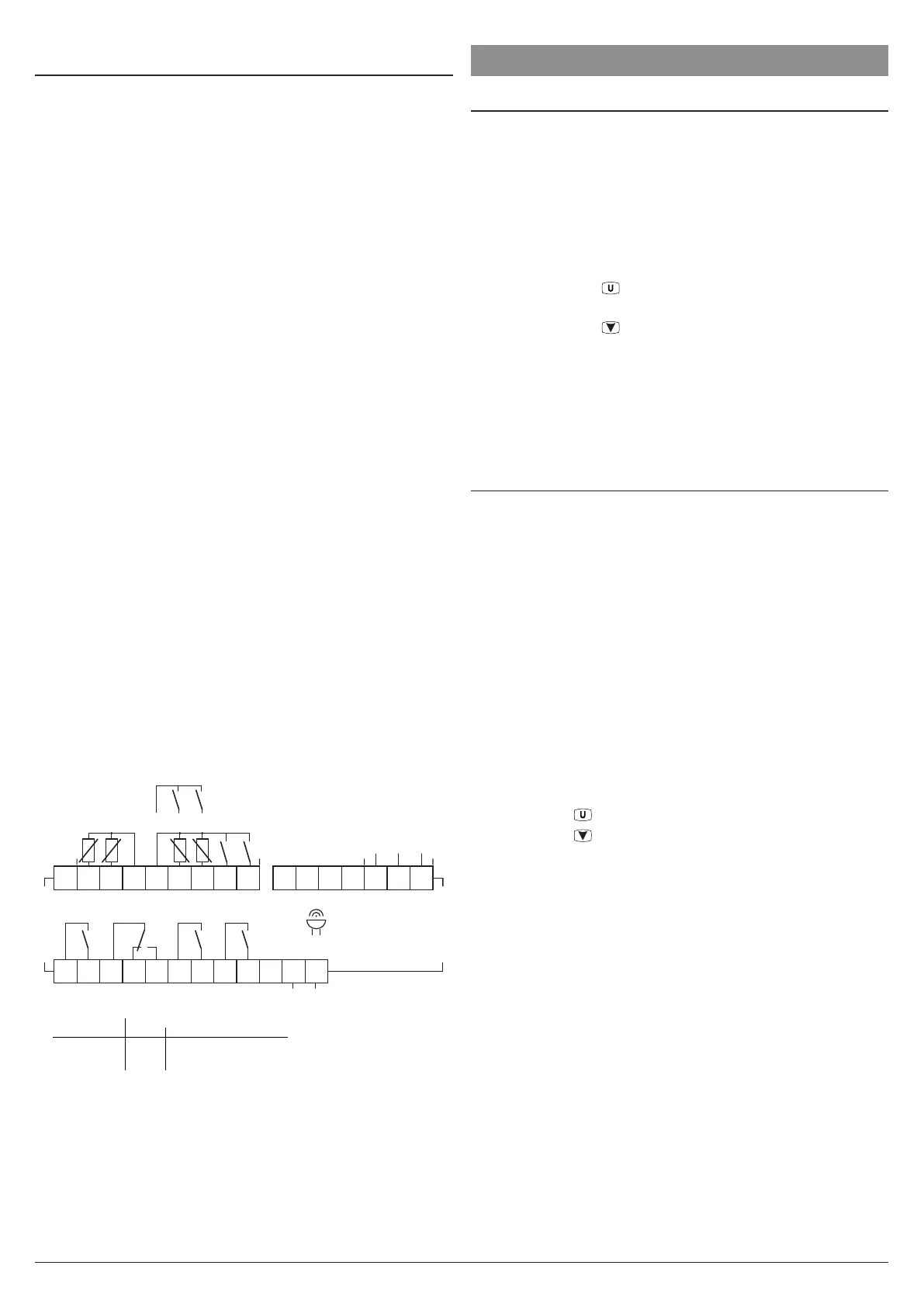
4.2.1 Electrical wiring diagram
1
2
3
4
5
6
7
8
9
10
11
1213
14
1516
Internal
Buzzer
Pr1 Pr2
DI1DI2
D+ D- GND
Pr3 Pr4
DI3DI4
Power
supply
Inputs RS485
2 A Gen.Use
10 A Res.
12 A Res. 30 LRA / 5 FLA
UL
X34
Out2:
Out1:
Out3,4:
8 (3) A
16 (9) A10 (4) A
4 (4) A
2 (1) A5 (1) A
EN
61810
EN
60730
10E5 cycles, 0 T 50 °C
17
18
19
20
21
22
23
24
25
26
27
28
NO
NO NO NO
NC
C
Out2
C
Out1
C
Out3
C
Out4
5. FUNCTIONS
5.1 ON/Stand-by function
The instrument, once powered up, can assume 2 different
conditions:
– ON: The controller uses the control functions.
– Stand-by: The controller uses no control function and the
display is turned OFF except for the Stand-by LED.
If a power failure occours and then power returns, the system
always sets itself in the condition it was in before the black-out.
The ON/Stand-by function can be selected:
– Pressing the key
for at least 1 s if parameter
t.UF = 3 or 5;
– Pressing the key
/AUX for at least 1 s if parameter
t.Fb = 3 or 5;
– Using the digital input if parameter i.oF = 7 or 15
(where o can be 1... 4);
– By programming a programmable event through the clock
(if present).
5.2 Normal, “Eco” and Turbo
operating modes
The instrument allows to pre-set up to 3 control Set Points:
SP Normal Set Point;
SPE Eco (economical) Set Point;
SPH Turbo Set Point.
Associated with each of these modes is present the corre-
spondent differential (hysteresis):
r.d Normal mode differential;
r.Ed Eco mode differential;
r.Hd Turbo mode differential.
The switching between these modes can be automatic or manual.
“Normal/Eco” mode operation
Can be used where it is necessary to switch between two
different operating temperatures (e.g.: day/night or working
days/holidays).
Normal/Eco mode can be selected manually:
– Pressing the
key if parameter t.UF = 2;
– Pressing the
/AUX key if parameter t.Fb = 2;
– By a digital input if parameter i.oF = 6
(where o can be 1... 4);
Normal/Eco mode can be selected automatically:
– After the door has been closed for time i.Et (switching
from Normal to Eco);
– When the door is opened if the SPE Set Point is active
from parameter i.Et (switching from Normal to Eco);
– After the door has been closed for time i.tt since activa-
tion of the SPE Set Point from parameter i.Et (switching
from Eco to Normal);
– At times defined through the clock by programming events
t.6 (switch to Eco mode) and t.7 (switch to Normal mode).
For further information see the paragraph on programming
events through the clock.