Ascon Tecnologic - X34 - OPERATING INSTRUCTIONS - PAG. 14
With 2 evaporators
The instrument can also be used to control defrosts in twin
evaporators systems (or with a single evaporator, but large
enough to require two defrost control areas) by means of two
defrost outputs and two probe inputs for the two evaporators.
Defrosts are always launched simultaneously for both evapo-
rators and therefore the output configured as 2d is always
activated simultaneously with the output configured as dF.
T
EP
Evaporator 1
Evaporator 2
T
2P
dF
2d
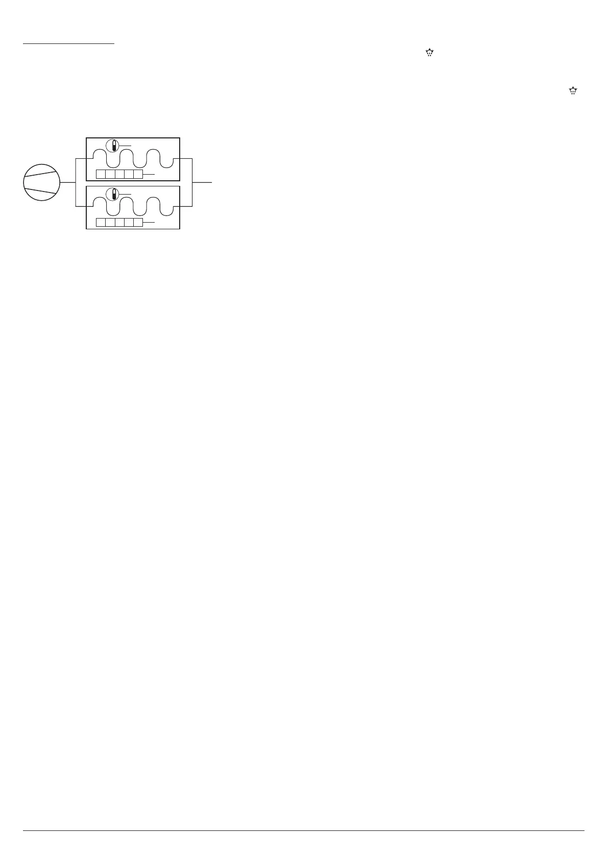
E.g.: Schematic example of plant with two evaporators, 2
probes and electric defrosters.
If the two evaporator probes are not used, the defrost end,
intended as deactivation of the defrost outputs, happens
separately at the end of the times defined at parameters d.dE
(for output dF which controls evaporator 1 defroster) and
d.d2 (for output 2d which controls evaporator 2 defroster).
However, the end of a defrost as a controller phase always
occurs when both times have elapsed.
If each evaporator is equipped with its own probe, an input
as evaporator probe 1 (i.P
o
= EP) and an input as evapora-
tor probe 2 (i.P
o
= 2E) must be configured.
In this case the instrument controls the defrosts using the
following criteria:
– Defrost is enabled when at least one of the two temperature
readings is below the temperature set at parameter d.tS;
– Defrost by temperature starts when at least one of the two
T
emperature readings
remains below the temperature set
at parameter d.tF for time d.St;
– The defrost end, in the sense of deactivation of the de-
froster command outputs dF and 2d in modes d.dt = EL,
in and no occurs separately for the two evaporators when
their respective temperatures sensed by the probes rise
above the values set at parameter d.tE (evaporator 1 with
probe EP) and d.t2 (evaporator 2 with probe 2E). If these
temperatures are not reached within the times set at pa-
rameters d.dE and d.d2 their respective defrosting actions
are interrupted. However, the end of defrost, as a control-
ler phase, occurs when both readings exceed the intended
values (or, if the temperatures are not reached, when their
maximum durations have reached).
If the selected defrost mode is of the type employing electric
heating and thermostating (d.dt = Et), the two defrost out-
puts dF e 2d behave as temperature controllers with heating
function with the their own Set Point: d.tE (evaporator 1) and
d.t2 (evaporator 2), both with hysteresis fixed at 1°C and
with reference to the respective temperatures measured on
the two evaporators.
If one of the two evaporator probes is not enabled or is in
error, its defrost behaves as with selection EL (during defrost
the defrost output remains always active).
Note: The “Dynamic Defrost” function and the thermostat-
ting function of the fans, always and only operate as
a function of the probe configured as EP (evaporator
1). If the control with the twin evaporator is not used,
it is recommended to set d.d2 = oF in order to avoid
unwanted influences on total defrost duration.
The defrost cycle in progress is shown on the instrument
with the lighting up of the LED.
In order to allow evaporator dripping, at the end of the de-
frost is possible to delay the compressor (ot output) restart
of the time set with parameter d.td. During this delay the
LED flashes to indicate the dripping in progress.
5.8.4 Defrosts in event of evaporator probe error
In event of evaporator probe error the defrosts occur at inter-
vals d.Ei with duration d.EE.
In the event that a probe error occurs, when the time left to
start or end of the defrost normally counted is less than that
set for the parameters related to the probe error conditions,
the defrost start or end occurs with the shortest time.
These functions are provided because, when the evapora-
tor probe is used, the defrost duration is usually set longer
than necessary (the time d.dE is a security time-out) and, in
the case the “Dynamic Intervals Defrost System” is used,
the interval is usually set longer than what is normally pro-
grammed into instruments that do not have these functions.
Note: In case of plants with double evaporator, the defrost
duration switching function acts only on parameter
d.dE relative to evaporator 1 (d.d2 remains at the same
value even if the probe configured as 2P is in error).
5.8.5 Defrost display lock
Through parameters d.dL and A.dA it is possible to define the
display behaviour during defrost.
The d.dL parameter can assume the following values:
on Locks the display on the last Pr1 probe temperature
readedfor all the defrost cycle and until, after defrost
end, the Pr1 temperature has not reached the lock
value or the value [SP + r.d] or is elapsed the time
setted on parameter A.dA.
Lb Shows the label dEF during the defrost cycle and of
PdF after the defrost, until, at defrost end, the Pr1
temperature has not reached the lock value or the
value [SP + r.d] or is elapsed the time setted on pa-
rameter A.dA.
oF The display continues showing the temperature meas-
ured by Pr1 probe during the defrost cycle.
5.8.6 Hot-gas defrost in centralized systems
The described operation is enable setting d.dt = HG.
With this mode is necessary to configure 3 outputs to set the
functions of:
– Liquid Solenoid Valve (output ot);
– Hot Gas Solenoid Valve (dF output);
– Aspiration Solenoid Valve (Au output with o.Fo = 3 configu-
ration).
In this configuration, during defrost only the dF output is ac-
tive, while before and after defrosting, the valves ot and Au
perform a sequence of timed operations described below.
As in all Hot Gas defrosts, also these systems use the heat
of the compressor exhaust gas to perform the defrost.
However given the conformation of these plants in which
the evaporators are all in parallel and the compressors are
centralized and therefore, not controlled by the instrument
(to adjust the temperature the instrument controls the Liquid
solenoid valve) it is necessary to use an output that controls
an Aspiration solenoid valve so that the evaporator that per-
forms the defrost is isolated from the system.
Similarly while defrosting, the Liquid solenoid valve (the