Ascon Tecnologic - X34 - OPERATING INSTRUCTIONS - PAG. 19
the RTC, the key action has priority on the event.
4 Pressing the key for at least 1 s activates/deactivates a
Turbo cycle.
5 Forces a programmed Switch-ON/Switch-OFF (Stand-
by) event - Pressing the key for at least 1 s switches the
instrument from the ON state to the Stand-by state and
vice-versa, until the next event. Therefore, if switch-ON/
Stand-by events are programmed using the RTC, the key
action has priority on the event.
6 HACCP Alarm Reset - Pressing the key for at least 1 s
resets stored HACCP alarms. The display confirms the
reset showing “---” for about 1 s.
7
HACCP Alarm Recording Disabled - Pressing the key for at
least 1 s disables/enables recording of the HACCP alarms.
After the selection is made the display shows for about 1 s:
Hon (HACCP alarms enabled) or
Hof (HACCP alarms disabled).
5.13 Clock programmable events
Programmable events are set using the 14 parameters
(c.01... c.14) contained in the
]
cE group.
After selecting the desired parameter, press the
key re-
peatedly to cycle through the following:
h..
oo
Hours (e.g. h.13);
n..
oo
Minutes (e.g. n.45);
d..
o
Day of the week (e.g. d.1);
t.
o
Type of event to be performed at the programmed time
(e.g. t.1).
Note: See “2.8 Scheduling events at defined times” a pagina
5 for details.
The days are numbered as follows:
d. 1 Monday;
d. 2 Tuesday;
d. 3 Wednesday;
d. 4 Thursday;
d. 5 Friday;
d. 6 Saturday;
d. 7 Sunday;
d. 8 every day;
d. 9 Monday, Tuesday, Wednesday, Thursday, Friday;
d.10
Monday, Tuesday, Wednesday, Thursday, Friday, Saturday;
d.11 Saturday and Sunday;
d.oF No day (event disabled).
The 14 event-programming parameters allow a maximum of
14 x 7 = 98 weekly events to be scheduled (using d. 8).
The following events can be programmed:
t.1 Switch instrument ON;
t.2 Put instrument in Stand-by;
t.3 Switch auxiliary output ON;
t.4 Switch auxiliary output OFF;
t.5 Start defrost (to enable scheduled defrosting, also
program d.dC = cL);
t.6 Switch to Eco mode (SPE);
t.7 Switch to normal mode (SP).
A manual intervention, e.g. to change the mode (Eco or Nor-
mal) or activate/deactivate the auxiliary output, is effective
only until the next scheduled event.
For example, if the instrument is in Eco mode and is forced
manually to Normal mode it will stay in Normal mode until
the next event that switches it to Eco mode.
Programming example
The user wishes to set the following events:
– 4 daily defrosts weekdays at 7:00, 12:00, 17:00 and 22:00;
– 2 defrosts every Sunday at 7.00 and 19.00
(also set d.dC = cL);
– 1 daily weekday switching from Normal to Eco mode at
20.00 and 1 switching from Eco to Normal mode at 6.00;
– No switches on Sundays;
– 1 daily weekday switching Aux output ON at 8.00 and
1 daily switching the Aux output to OFF at 21.00;
– No switches on Sundays.
Event Parameter Hour Minutes Days Event
Work day defrost 1
c.01 h.07 n.00 d.10 t.5
Work day defrost 2
c.02 h.12 n.00 d.10 t.5
Work day defrost 3
c.03 h.17 n.00 d.10 t.5
Work day defrost 4
c.04 h.22 n.00 d.10 t.5
Sunday defrost 1
c.05 h.07 n.00 d.7 t.5
Sunday defrost 2
c.06 h.19 n.00 d.7 t.5
ECO mode
c.07 h.20 n.00 d.10 t.6
Nomal mode
c.08 h.06 n.00 d.10 t.7
Aux on
c.09 h.08 n.00 d.10 t.3
Aux off
c.10 h.21 n.00 d.10 t.4
c.11...... c.14
h.00 n.00 d.oF t.oF
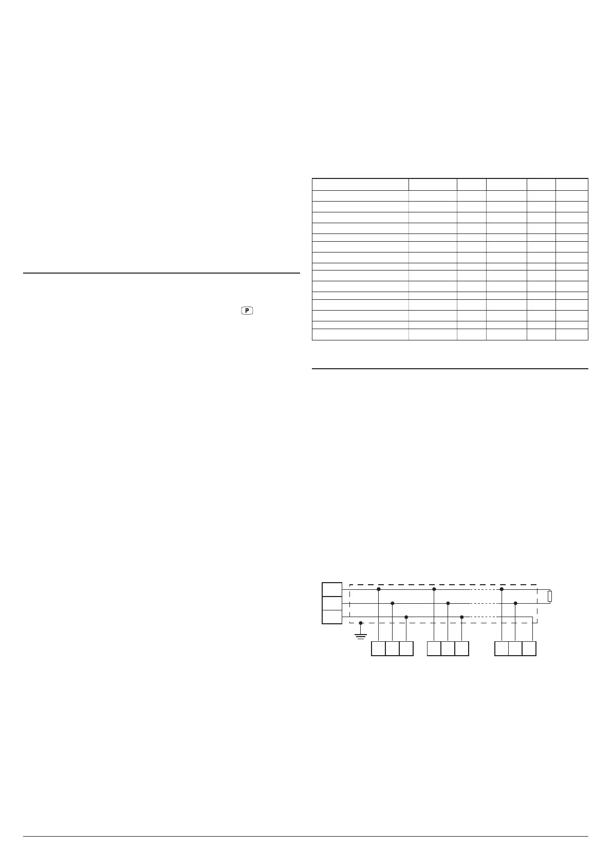
5.14 RS485 Serial Intefarce
The instrument can be equipped with a RS485 serial com-
munications interface, by means of which it is possible to
connect the controller to a network to which other instru-
ments (PLC controllers) are connected, all depending typi-
cally on a personal computer used as plant supervisor.
Using a Personal Computer it is possible to acquire all
the function information and to program all the instrument
configuration parameters. The software protocol adopted fa
MODBUS RTU type, widely used in several PLC and super-
vision programs available on the market (X34 series protocol
manual is available on request).
The instrument has two terminals called D+ and D- that must
be connected to all network terminals with the same label.
For wiring the line, it is advisable to adopt a 3-pole wired and
shielded cable connected as shown.
D+
D-
GND
(OP/PC/PLC)
RS485
Interface
shield
14
Rt
120Ω
15 16
D+ GNDD-
X34 no. 1
14 15 16
D+ GNDD-
X34 no. 2
14 15 16
D+ GNDD-
X34 no. 31
The interface circuit allows the connection of up to 32 instru-
ments on the same line.
To maintain the line in rest conditions a 120
W
resistance (Rt)
must be connected to the end of the line.
If the instrument is equipped with a serial interface, the pa-
rameters to be programmed are those present at parameters
group ]tS:
t.AS Address of the station. Set a different number for
each station, from 1 to 255.
t.br Serial interface baud rate. Settings available:
1 = 9600 baud, 2 - 19200 baud, 3 - 38400 baud.