Doc ID : ADR111A_IM_01
Ref ID : ADR111A/IM/TC
Rev No. : 04
Page No. : 125 of 127
ADR111A /
ADR211A
11.4 Relay Testing
11.4.1. Relay Calibration & Measurement
Before conducting actual test, confirm relay calibration by following method.
Connect ADR111A/ ADR211A relay to current injector and timer.
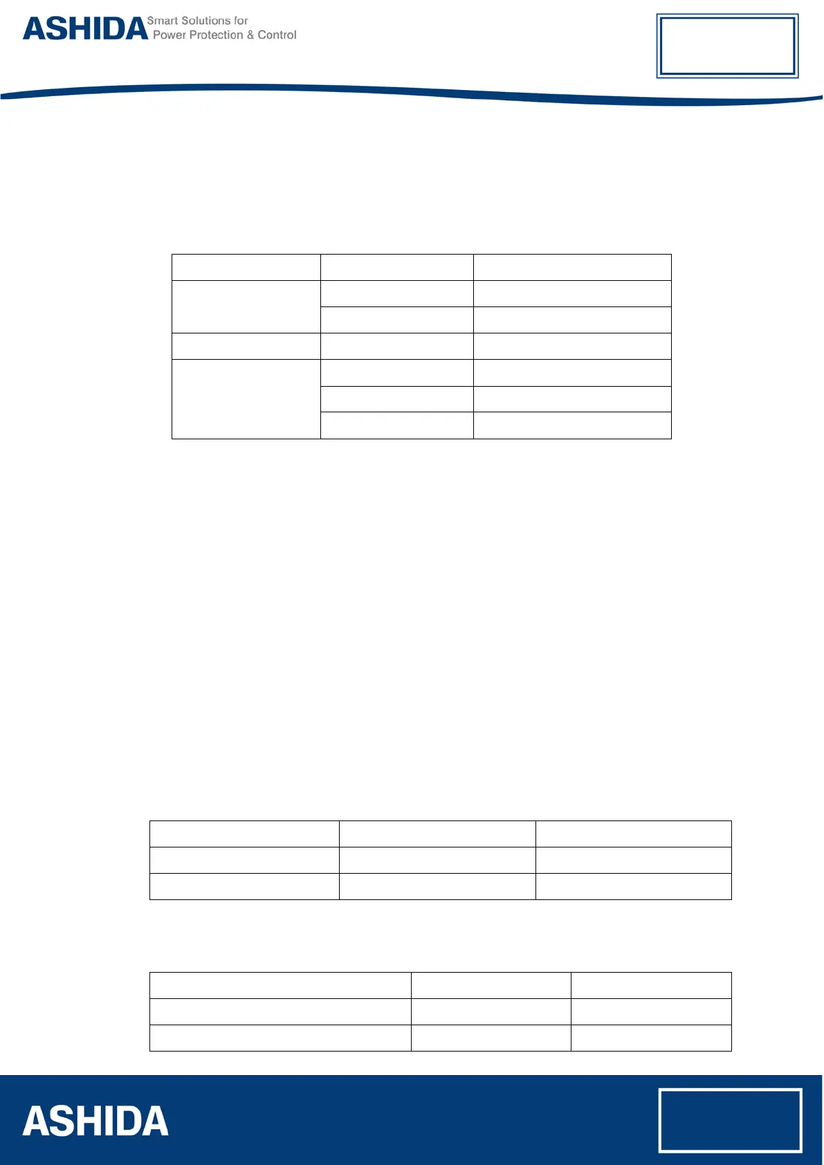
Following chart shows terminal numbers of connections.
Source Terminal Relay Terminal Relay Connection
Current Source
A1 – A2 Current CT _1A
A3 – A4 Current CT _5A
Power Supply (+ / -) A15 – A16 Power Supply (+ / -)
Logic Output
A9 – A10 TRIP contact
A11 – A12 Alarm contact
A13 – A14 BF contact
Step1. Connect all terminals as per the chart.
Step2. Adjust rated CT Secondary Current 1A/5A. Observe the current value from
measurement menu. The actual current should match with relay display.
11.4.2. Pick up and Trip Test
1. Connect current source at CT terminals 1A/5A current input terminal.
2. Set current setting value to 100% i.e. 1A/5A, TMS at Minimum (x0.01) value.
3. Start current injector & increase current value till relay get pick up and trip. The operating
value should be within 1 to 1.1 times of set pickup value.
4. Select the Curve Normal Inverse 1 and Set the TMS at 1.00.
5. Connect the Trip contact to Timer.
6. Set and apply 2 times current value and measure the timing on timer.
7. The measured timing should be ±5 % of actual timing (10.029 Sec).
Setting I>: ________ I> TMS =: _______
Threshold Theoretical Value Relay Value
I> Threshold ________A ________A
I> Drop Threshold ________A ________A
Time Delay Setting = _________
IDMT Characteristics = ________ 10 Times _________Sec. (take value from selected curve)
Threshold Relay
Time Delay at 2 times of I> setting ________ms ________ms
Time Delay at 10 times of I> setting ________ms ________ms