Doc ID : ADR111A_IM_01
Ref ID : ADR111A/IM/I&P
Rev No. : 04
Page No. : 37 of 127
ADR111A /
ADR211A
2.3.9 Power Supply Connections
These should be wired with 1.5 mm PVC insulated multi-stranded copper wire terminated
with M4 ring terminals. The wire should have a minimum voltage rating of 300 V RMS.
As per the application, in case auxiliary supply input of the relay needs to be wired, then
adequate care should be taken to wire as per polarity marking on the Terminal sticker at the
rear of the relay. The supply range is also mentioned on the Terminal sticker and before
energising, care should be taken to confirm that the auxiliary supply being wired is within
range.
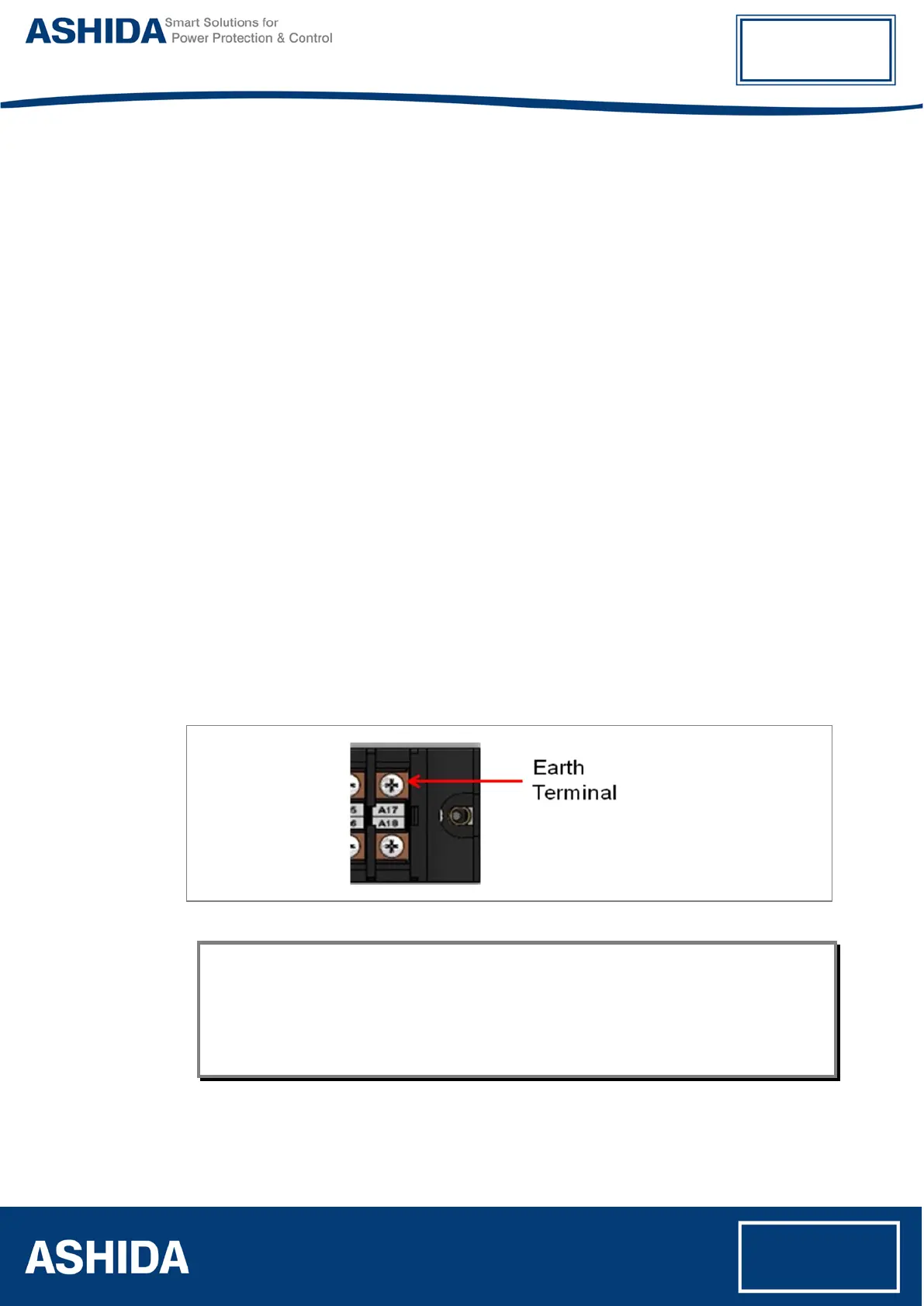
2.3.10 Earth Connection
Every device must be connected to the cubicle earthing bar. Earthing terminal is provided on
back side of the relay. Ensure that the relay earthing is connected to the local earth bar. With
several relays present; make sure that the copper earth bar is properly installed for solidity
connecting to the earthing terminal of each relay equipment box.
Before energizing the equipment, it must be earthed using the protective conductor terminal,
(if provided) or the appropriate termination of the supply plug in the case of plug connected
equipment. The protective conductor (earth) connection must not be removed since the
protection against electric shock provided by the equipment would be lost. The
recommended minimum protective conductor (earth) wire size is 2.5 mm² or as per industries
standard practice. The protective conductor (earth) connection must be of low-inductance
and as short as possible.
Note: To prevent any possibility of electrolytic action between brass or copper ground conductors
and the rear panel of the product, precautions should be taken to isolate them from one
another. This could be achieved in several ways, including placing a nickel-plated or
insulating washer between the conductor and the product case, or using tinned ring
terminals.