VIPEDIA-12 Products – Installation Guide
U-0641-0344.docx – Issue: 8 complete, approved
Page 12 of 52
4. Position the hardware bypass audio switch (DBB switch) as required.
See Section “7.6 Expansion Unit Connection” (page 45
) for expansion unit connection and DBB
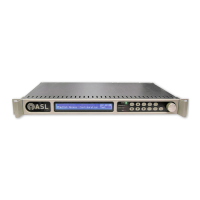
5. If the unit is fitted with Network Card, fit the SFP module(s) if used.
6. Connect the field wiring as required.
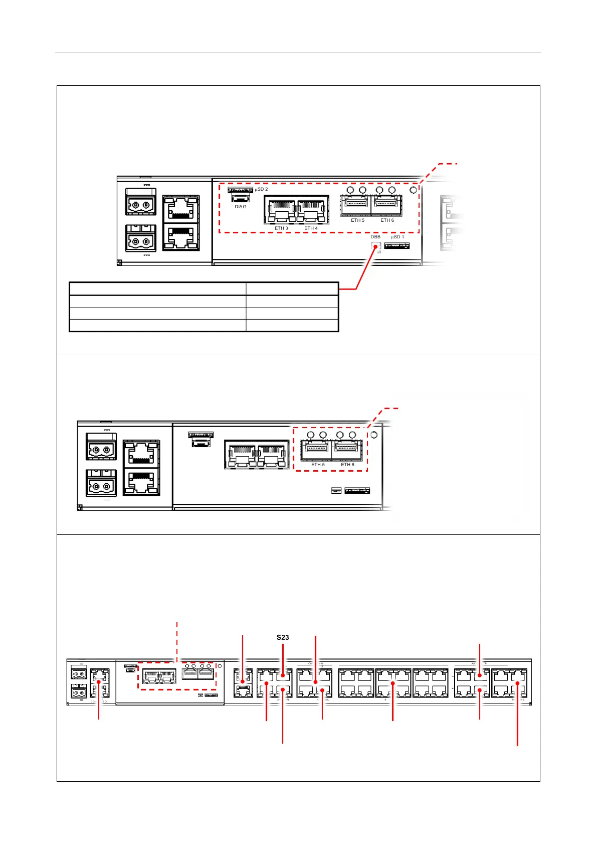
Refer to Section “7.1 VIPEDIA-12 Connections (Rear Panel)” (page 16) for pinout details.
IN
+-
18-40V 2A
18-40V
2A
1
2
CONTACTS OUT
1 - 6
7 - 12
CONTACTS OUT
DBB IN 1
DBB OUT 1
µSD 1
DBB
S M
µSD 2
DIA G.
ETH 3 ETH 4
ETH 5 ETH 6
Card is fitted)
Factory Default (stand-alone unit)
Expansion Unit (DBB Member 2, 3, and 4)
Base Unit of a DBB Group (DBB Member 1)
IN
+-
18-40V 2A
18-40V
2A
1
2
CONTACTS OUT
1 - 6
7 - 12
CONTACTS OUT
DBB IN 1
DBB OUT 1
µSD 1
DBB
S M
µSD 2
DIA G.
ETH 3 ETH 4
ETH 5 ETH 6
SFP cages for optional SFP
modules:
• MM (multimode fibre)
module
• SM (single mode fibre)
module
• RJ45 (copper) module
(refer to ASL for availability and
compatibility)
IN
+-
18-40V 2A
18-40V
2A
1
2
CONTA CTS OUT
1 - 6
7 - 12
CONTA CTS OUT
DBB IN 1
DBB OUT 1
ETH 1 RS232
ETH 2 AMP CTRL
1-4 5-8
CONTROL
CONTA CTS IN
9-12
CONTA CTS IN
1 2
7 8
3 4 5 6
9 10 11 12
AUDIO INPUTS
1-4 5 -8
1-4 5 -8 9-12
9-12 MIC AUX 1
MIC AUX 2
A
B
AUDIO OUTPUTS
µSD 1
DBB
S M
µSD 2
DIA G.
ETH 3 ETH 4
ETH 5 ETH 6
(Outputs)
Expansion
(Inputs)
Serial Interfaces
Auxiliary
(on Network Card)
Control