3. Device installation and start-up
PHG 700C / 701C User Manual Page 10 of 47
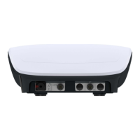
Figure 3.3. Laser therapy sockets
Operating notes for operation with the scanning laser applicator mounted on a stand:
• The stand with a unit and applicators shall be placed near mains socket with power input 230V and 50/60Hz,
so that the change of stand position is not limited by the mains cable.
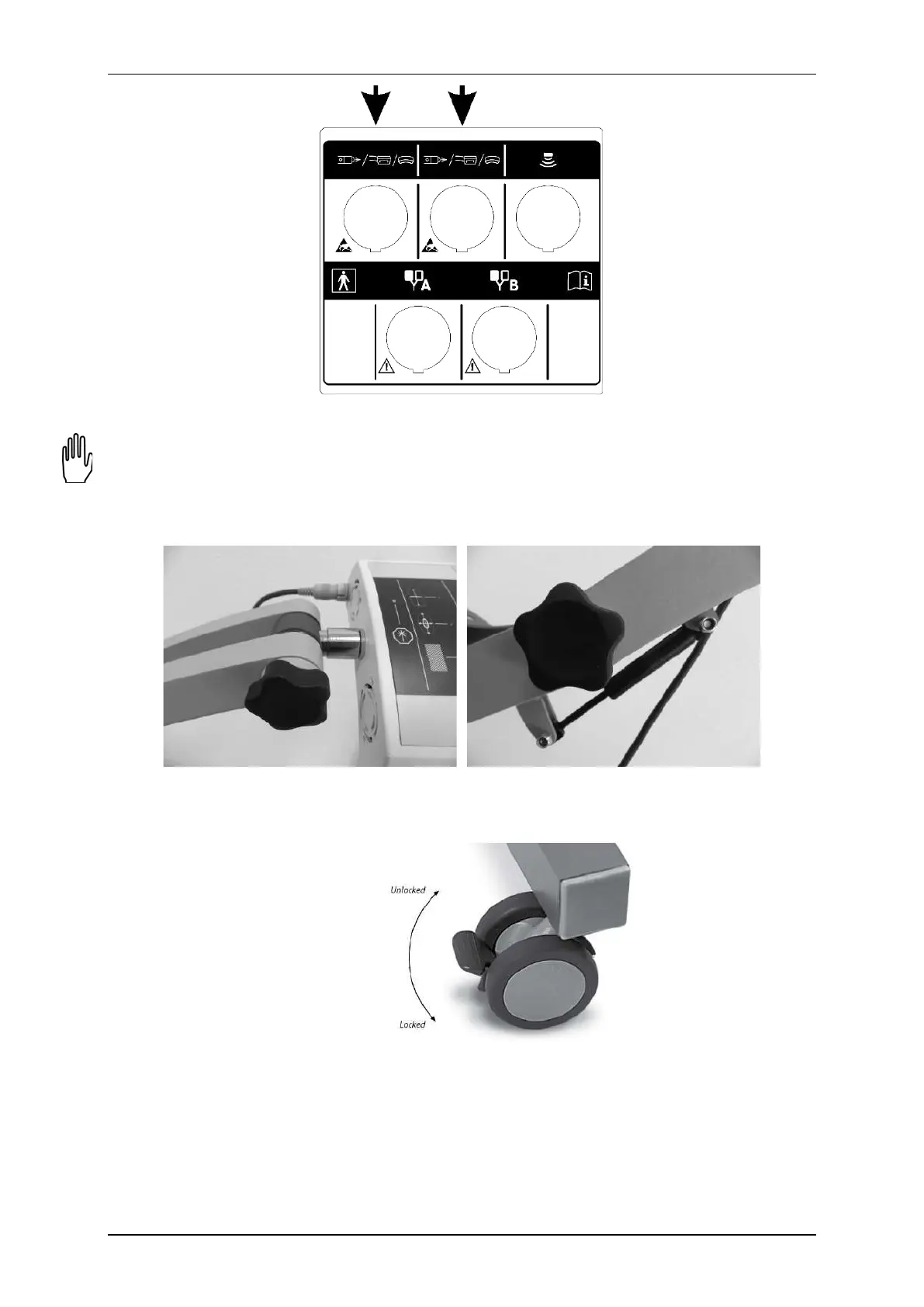
• When adjustment of scanner right position is difficult it is recommended to loosen or turn (depend on need)
handwheel locking the arm of the stand or handwheel locking the laser scanner (both handwheels are
presented in Figure 3.4).
Figure 3.4. Handwheels – scanner and arm of the stand
• To protect the stand from unintentional change of its position it is recommended to lock wheel brakes –
brake must be pressed to the floor. To release the brake, lift it up (wheel with brake is shown in Figure 3.5).
Figure 3.5. Wheel with brake
• To disassemble the controller from the shelf it is recommended to unscrew the bolts mounted to the shelf.
• To disassemble the scanning applicator, with one hand pull the mounting protection ring and using the
other one release the scanner from the mounting socket.
• Other interconnecting cables shall be located to enable free change of position of the stand and scanning
position adjustment.
 Loading...