3. Device installation and start-up
PHG 700C / 701C User Manual Page 12 of 47
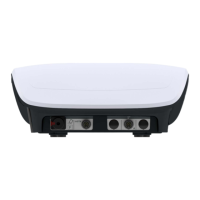
3.1.7 Patient’s stop switch connection
Patient’s stop switch should be connected into the socked marked as STOP.
Figure 3.8. Patient’s stop switch socket
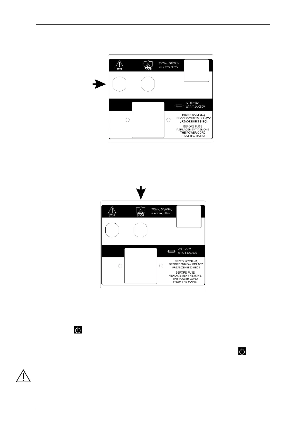
3.1.8 Connection of DOOR remote connector
DOOR remote connector socket is located on the rear panel of the unit. In order to perform laser treatment
procedures, insert the plug marked DOOR into the socket.
Figure 3.9. DOOR remote connector socket
3.1.9 First operation
Connect the unit to mains supply with delivered detachable mains cable. Switch the mains supply on. Then press
the STANDBY key to start the operation. After switching the mains supply on proper work of all blocks are
tested.
In the case of battery operation, please hold on for at least 3 seconds the STANDBY key . Extension
of the holding time prevents unintentional activation during transport.
If after switching on mains supply the display is illegible and no light indicator is illuminated, check whether
mains fuse or mains cable operate correctly. Care shall be given to apply fuses with rating given on the name
plate. If fuse and cables are working properly, contact the authorized service.
 Loading...