OM226142 rev C
9
• Battery (B)
• Static switch: Static inverter switch (SSI) and Static Bypass switch (SB)
• Manual Bypass (MB)
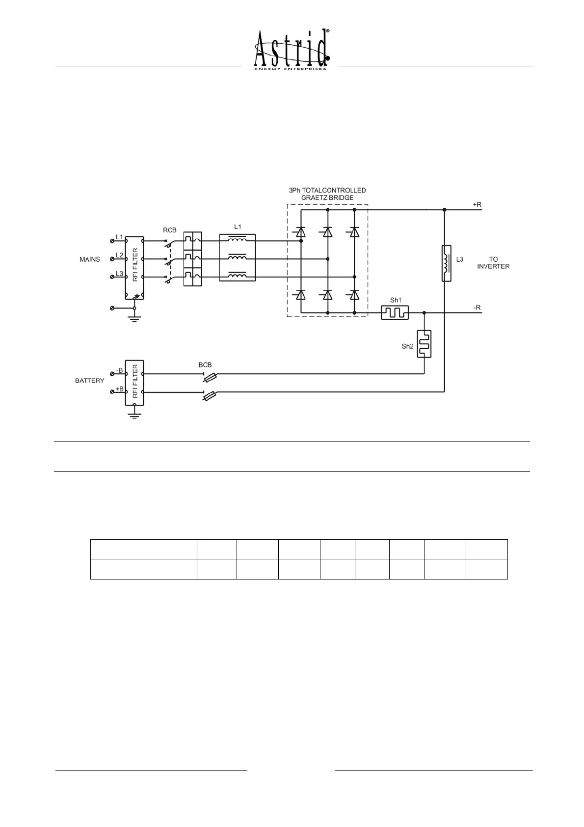
2.1 RECTIFIER / BATTERY CHARGER
The rectifier/Battery charger converts the AC input voltage to DC voltage, feeding the
inverter and keeping the battery charged.
Picture 2 – Rectifier
NOTE
On HALLEY/E 40÷80kVA RCB is a fused switch and BCB is not installed.
The AC input voltage is filtered by the inductor L1 and then converted into DC by the 6
pulses phase-angle controlled rectifier, composed by six thyristors. The typical harmonic
distortion of the current absorbed by a 6 pulses rectifier is shown in the table below:
Harmonic order 1 5 7 11 13 17 19
THD
Amplitude (In/I1) 100 % 19,6 % 13,8 % 8,5 % 7,0 % 5,1 % 4,4 % 27,0 %
The inductor L3 reduces the current ripple generated by the inverter so that the battery life
is improved. During the battery discharge the inductor L3 works like a short-circuit, so that
there’s no voltage drop and the battery capacity can be completely used. The rectifier is
designed to recharge and keep charged Sealed Lead Acid Batteries, although Open-type
Lead Acid or Ni-Cd batteries can be used. Following to the manufacturer’s instructions,
each type of battery must be charged according to its manufacturing technology. Basically
there are two different charging methods:
• ONE CHARGING LEVEL (FLOATING CHARGE)
• TWO CHARGING LEVELS (FLOATING / BOOST CHARGE)
The double-level charging mode is generally used with Open-type Lead Acid or Ni-Cd
Batteries and it’s provided as option (see section OPTIONS for further details).