OM226142 rev C
34
5.2.4 Electrical connection
The electrical connection is part of the work which is normally provided by the supplier that
carries out the electrical installation and not by the UPS manufacturer. For this reason, the
following recommendations are only an indication, as the UPS manufacturer is not
responsible for the electrical installation.
In any case we recommend to carry-out the installation and the electrical connections of
the input and output in compliance with the local standards.
During the electrical installation take particular care to check the phase rotation using a
suitable instrument.
The terminals are positioned at the front of the UPS and they can be accessed by opening
the front door.
WARNING
The connection to the mains must be carried out with protection fuses or circuit breakers
between the mains and the UPS.
The use of residual current devices in the line supplying the UPS is unadvisable.
The leakage current due to the RFI filters is rather high and it can cause spurious
tripping of the protection device.
According to the EN62040-1 standard, in order to take into account the UPS’ leakage
current, residual current devices having adjustable threshold can be used.
The recommended section of the connection cables is shown in the following tables.
UPS (kVA) 20 30 40 60 80
Input fuses (A)
Rectifier 3x50 3x80 3x150 3x200 3x200
Bypass - - - - -
Input cables (mm
2
)
Rectifier 4x10 4x25 4x35 4x50 4x70
Bypass - - - - -
Output cables (mm
2
)
4x10 4x25 4x35 4x50 4x70
Battery cables (mm
2
)
2x16 2x25 2x50 2x50 2x70
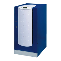
5.2.4.1 Terminal board
Picture 24 – Terminal board UPS 20-30kVA
Picture 25 – Terminal board UPS 40÷80kVA