Do you have a question about the Astronics OmniBusII and is the answer not in the manual?
Overview of the OmniBus II family of products for avionics databus communication.
Details on different host platform, protocol, and channel count combinations for OmniBus II products.
Description of common avionics databus standards supported by OmniBus products.
Lists additional documentation available for OmniBus interface operation and programming.
Information on how to contact Ballard Technology for technical support and sales.
Information on product updates and registering for a support account.
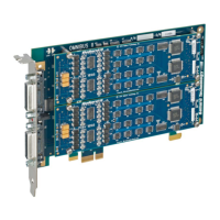
Procedure for physically installing the OmniBus II PCIe/PXIe card into a computer system.
Instructions for installing the necessary software drivers for the OmniBus II card.
Steps to assign a unique card number and verify the installed card's functionality.
Guidelines for connecting the PCIe/PXIe card to the relevant avionics databuses.
Description of CoPilot software for databus analysis and simulation with OmniBus products.
Information on using the BTIDriver API to create custom applications for OmniBus products.
Details on the PCI Express interface features for OmniBus II PCIe and PXIe cards.
Explanation of the three types of on-board built-in tests (PBIT, IBIT, CBIT) for card operation.
Information on the IRIG time signal capabilities for device synchronization.
Description of bidirectional TTL level discrete I/O capabilities on OmniBus II cores.
Details on the 16 avionics shunt discretes for signaling, status, and load driving.
Explanation of the clock source selection switch for PXIe compatibility.
Details on the PXIe trigger signals supported and their access via API functions.
How to interface PXIe Trigger signals with protocol sync and trigger definitions.
Accessing useful PXIe card status information through API parameters.
Information on PXIe card installation slots and their corresponding glyphs.
Lists part numbers for OmniBus II PCIe carrier boards and their configurations.
Lists part numbers for OmniBus II PXIe carrier boards and their configurations.
Details on MIL-STD-1553 modules, part numbers, and functionality levels.
Information on ARINC 429 I/O modules, part numbers, and capabilities.
Details on ARINC 708 I/O modules, part numbers, and features.
Information on ARINC 717 I/O modules, part numbers, and capabilities.
Description of the primary user interface connector (LFH receptacle) and its specifications.
General pin designation overview for all OmniBus II products.
Specific pin definitions and connector pinouts for various OmniBus II modules.
Information on standard cable assemblies available for connecting OmniBus II products.
Explanation of bus termination requirements for MIL-STD-1553 and ARINC 708 databuses.
Discussion on transformer and direct coupling methods for MIL-STD-1553 and ARINC 708.
| Brand | Astronics |
|---|---|
| Model | OmniBusII |
| Category | Computer Hardware |
| Language | English |