MODULE CONFIGURATIONS
S = Single function
M = Multifunction
P = Multifunction with parametrics
Table 6.3—MIL-STD-1553 Module Part Numbering
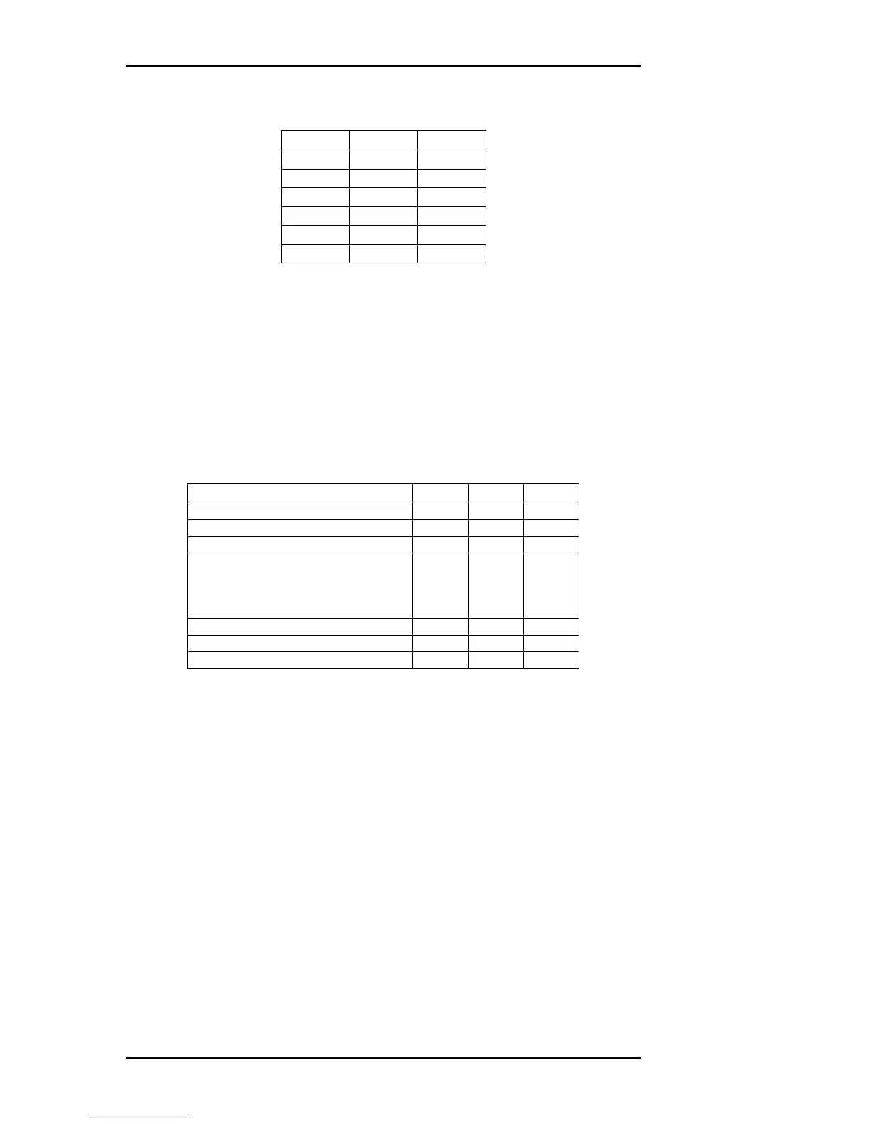
Each MIL-STD-1553 channel is available in three levels of functionality (sum-
marized in the table below). All levels provide at least single terminal Bus Con-
troller, Remote Terminal, and Monitor operation and user-configurable RT
response time. Advanced features include multi-terminal simulation (up to 32)
with concurrent monitoring and protocol error injection (word, gap, and message
errors). Level P MIL-STD-1553 modules provide variable transmit amplitude
and zero crossing distortion.
Level Number used in Part No.→
Number of Simultaneous Terminals
Configurable RT Response Time
Filtering for terminal address
Concurrent terminal monitoring
Variable Transmit Amplitude
Table 6.4—MIL-STD-1553 Level Function Definition
The MIL-STD-1553 modules also contain Avionics Discrete I/O, see Section 4.5
for more details.
6.3.1 Software-Selectable Bus Termination
Each databus on all OmniBus MIL-STD-1553 modules has a 75-ohm termination
resistor that can be switched across the direct-coupled terminals under software
control. When transformer coupling is used, the direct-coupled termination re-
sistance must be off, and external couplers and terminators are required. See
Appendix A for more information about bus termination and transformer versus
direct coupling.
6-2 OmniBus II PCIe/PXIe User’s Manual