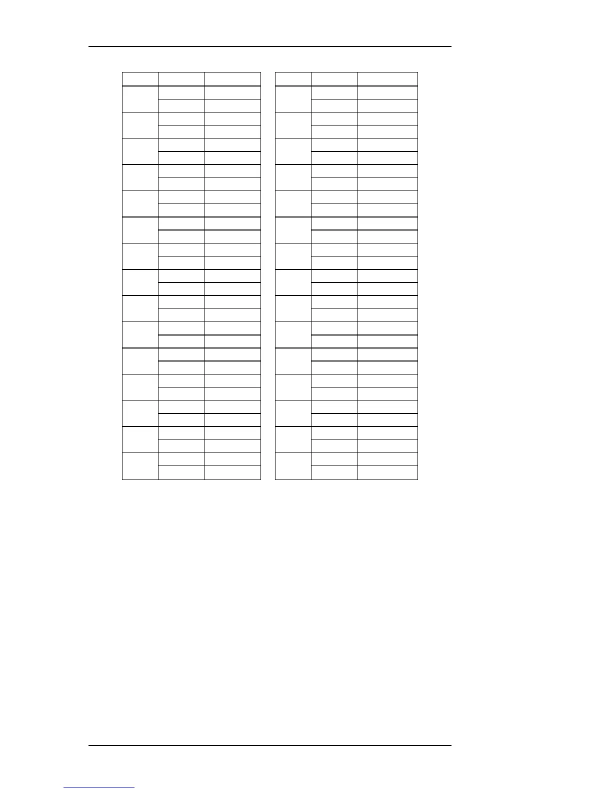
CONNECTOR PINOUTS
1
16
2
17
3
18
4
8 BUS6N
19
38 BUS14N
5
20
6
21
7
22
8
23
9
24
19 CDIO5 49 CDIO6
10
25
11
26
12
27
13
28
14
28 BUS1P
29
58 BUS9P
15
30
Table 7.1—General pin designations
7.3 Module-Specific Wiring
The meaning and use of the databus signals on the LFH connector depends on
the protocol and functionality of the associated module. This section provides
channel definitions and connector pinouts for the more common OmniBus II
modules. Listings for the “16036 Pin” give the connector and pin number for
the signal when a Ballard 16036 cable is used. See Section 7.4 for more infor-
mation on cables.
7-2 OmniBus II PCIe/PXIe User’s Manual