OMNIBUS II FEATURES
hardware and host communication. Initiated test resets the card and is not in-
tended to be performed while the card is configured or running.
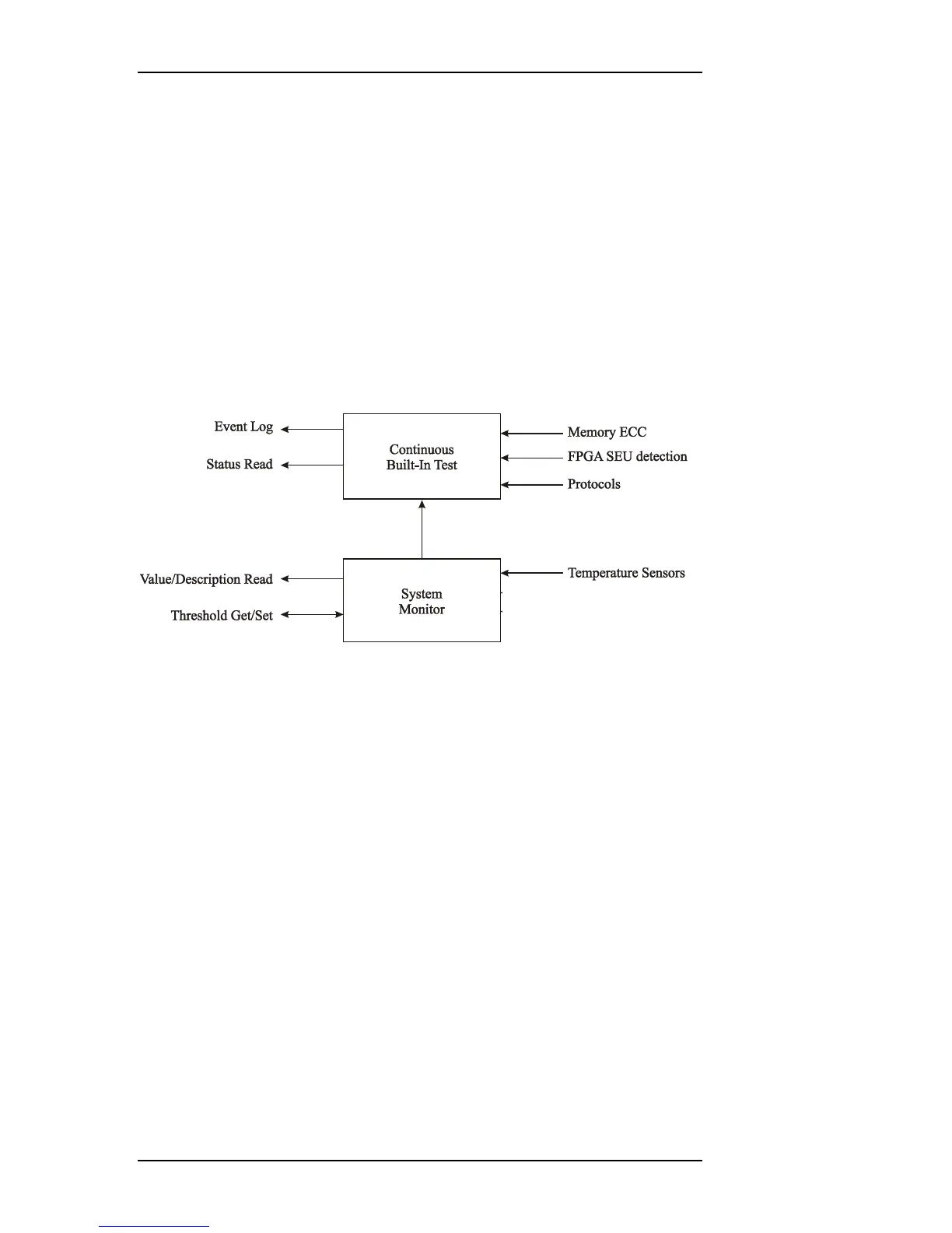
4.2.3 Continuous Built-in Test (CBIT)
During card operation, dedicated hardware constantly monitors multiple internal
modules for errors. These sources include error detection/correction circuits for
system memory and FPGA, protocol specific tests, and the system monitor (see
Figure 4.1). Status of these tests may be accessed through the API via polling or
interrupts.
The system monitor polls temperature data from sensors located on the card. Pre-
sent values, as well as historic minimum and maximum values, can be read from
the card. The API allows for setting of user temperature limits and enabling noti-
fication of exceeded limits. If temperature sensor measurements exceed built-in
system limits, card operation will be halted to protect the system.
Figure 4.1—Built-in test and System monitor architecture
4.3 IRIG Timer
An IRIG time signal contains a human-readable binary coded decimal (BCD)
time value in days, hours, minutes, seconds, etc. and can be used to synchronize
many devices. This allows timing data from all compatible devices to be easily
correlated.
The IRIG circuit can be configured as either a master or a slave. The IRIG timer
pin is driven by the bidirectional buffer only when the IRIG timer is configured
as a master. When the IRIG timer is configured as a slave, it will expect the IRIG
signal to come from an external device.
The OmniBus II devices internally use a binary system timer that is free running
and keeps time until either set by software or synchronized to an IRIG signal
when configured as a slave. This system timer is also the source for the IRIG in-
terface when configured as a master. The system timer has a resolution down to
one nanosecond.
IRIG data can be encoded using Pulse Code Modulation (PCM), Modified Man-
chester Modulation, or Amplitude Modulation (AM). The OmniBus II family
supports PCM master, PCM slave, AM master, and AM slave modulation modes.
4-2 OmniBus II PCIe/PXIe User’s Manual