OMNIBUS II FEATURES
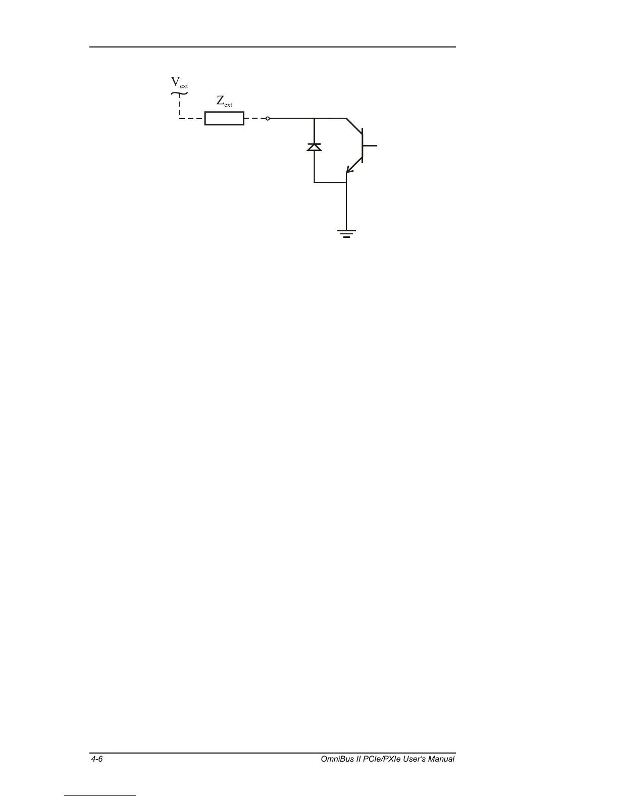
Figure 4.3—OmniBus II Discrete Shunt Output Circuit
4.5.4 Shunt Output Considerations
Limits: The OmniBus II discrete shunt outputs are open-ground switches capable
of sinking up to 200mA. The discrete outputs can withstand up to 35 VDC and
are capable of interfacing with industry standard avionics discrete signals.
Self-Monitor: The OmniBus II discrete shunt output circuits can be monitored
by corresponding OmniBus II discrete input circuits. Writing to a discrete can
drive an enabled output, and reading from that discrete, reports the current state
of the input. Once the output is driven, there is a finite period of time before the
change of state on the corresponding input is detected. This delay (approximately
30 µs) is due to the latency of the host system and the analog delay of the input
and output circuitry.
Over-Load/Fault Reporting: The OmniBus II discrete shunt output circuits
contain current limiting and thermal shutdown features. If a user attempts to sink
too much current through an output discrete circuit, the output will begin current
limiting. This is accomplished by increasing the resistance through the output,
which causes the power dissipation and therefore the temperature to increase.
The output continues to limit the current until the thermal limit is reached and
then the output is automatically shut down. Once an output is shut down due to a
fault, the output remains disabled until both the fault is cleared and the user
drives the output again. For this reason, it is important that the user corrects fault
conditions before attempting to drive the output.
High Current Drive: Each shunt output is capable of sinking up to 200 mA of
current. However, the user can wire multiple outputs in parallel to increase the
maximum current sinking capability.
Power-On: After power-on, the shunt discrete I/O is in its default state with out-
puts open (high impedance).
4-6 OmniBus II PCIe/PXIe User’s Manual