INTRODUCTION
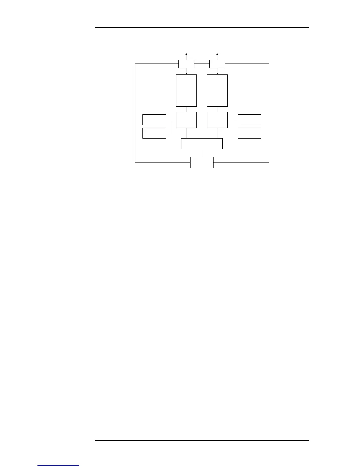
Figure 1.3—The two-core architecture of OmniBus II PCIe/PXIe card
The easiest way to operate OmniBus products is with CoPilot®, Ballard Tech-
nology’s databus analyzer and simulation software. Alternately, software devel-
opers can write their own software applications using the included BTIDriver™
API (Application Program Interface).
1.2 OmniBus II Configurations
The OmniBus family includes products with many different host platform, proto-
col, and channel count combinations. A given OmniBus part number is produced
in the factory by mounting protocol-specific modules on the required host plat-
form.
Note: OmniBus products are not user-configurable. Do not attempt to
swap one module type for another one with a different part number. If a
module is exchanged, it must be with an identical module. OmniBus
products may be upgraded with additional channels or protocols, but
this must be done at the factory.
The assembly part number characterizes the configuration of an OmniBus prod-
uct. The assembly part number is designated by groups of characters separated by
dashes. The first group of characters in the assembly part number is the part
number of the main board (eg. 212 for a two module PCIe card), the second
group is the part number of the module in the Core A position, and the third
group is the part number of the module in the Core B position. A more detailed
description of the individual part numbers may be found in Chapter 6.
The complete assembly part number is printed on the main OmniBus board. If
the modules are visible, each group of numbers in the assembly configuration
that represent modules should match the part numbers printed on the corre-
sponding modules. The configuration of an installed OmniBus product may be
determined by running the test program described in Chapter 4.
SDRAM
PCIe
Connector
1:2 PCIe Switch
Protocol
Module
B
Core A
FPGA
Core B
FPGA
Flash
SDRAM
Flash
Protocol
Module
A
P1 P2
Avionics
Databuses
Avionics
Databuses
1 Lane PCIe
OmniBus II PCIe/PXIe User’s Manual 1-3