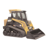
14. Disconnect the main oil cooler line from the fitting
at the filter. (fig. 9-13)
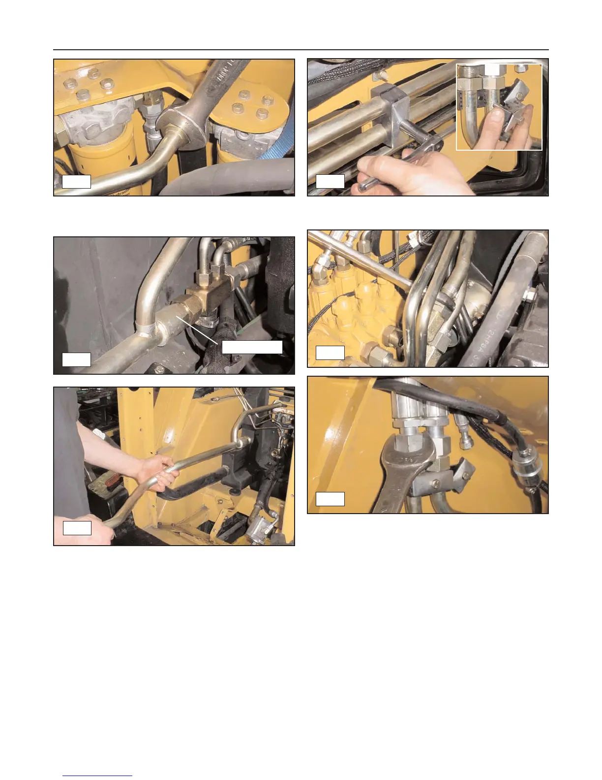
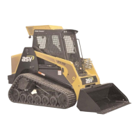
15. Disconnect the main oil cooler line from the junc-
tion block, then remove it from the machine.
(fig. 9-14, 9-15)
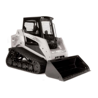
16. Remove the clamps securing the auxiliary
hydraulic lines to the chassis. (fig. 9-16)
17. Disconnect the auxiliary hydraulic lines from the lift
arm control valve and the hoses leading to the
quick coupler lines on the lift arm. (fig. 9-17, 9-18)
9-4
Rubber Track Loader
9. Hydraulic Reservoir
9-13
9-14
Disconnect
9-15
9-17
9-16
9-18