Manual, F/T Sensor, Ethernet Axia
Document #9610-05-Ethernet Axia-09
Pinnacle Park • 1031 Goodworth Drive • Apex, NC 27539 • Tel:+1 919.772.0115 • Fax:+1 919.772.8259 • www.ati-ia.com
19
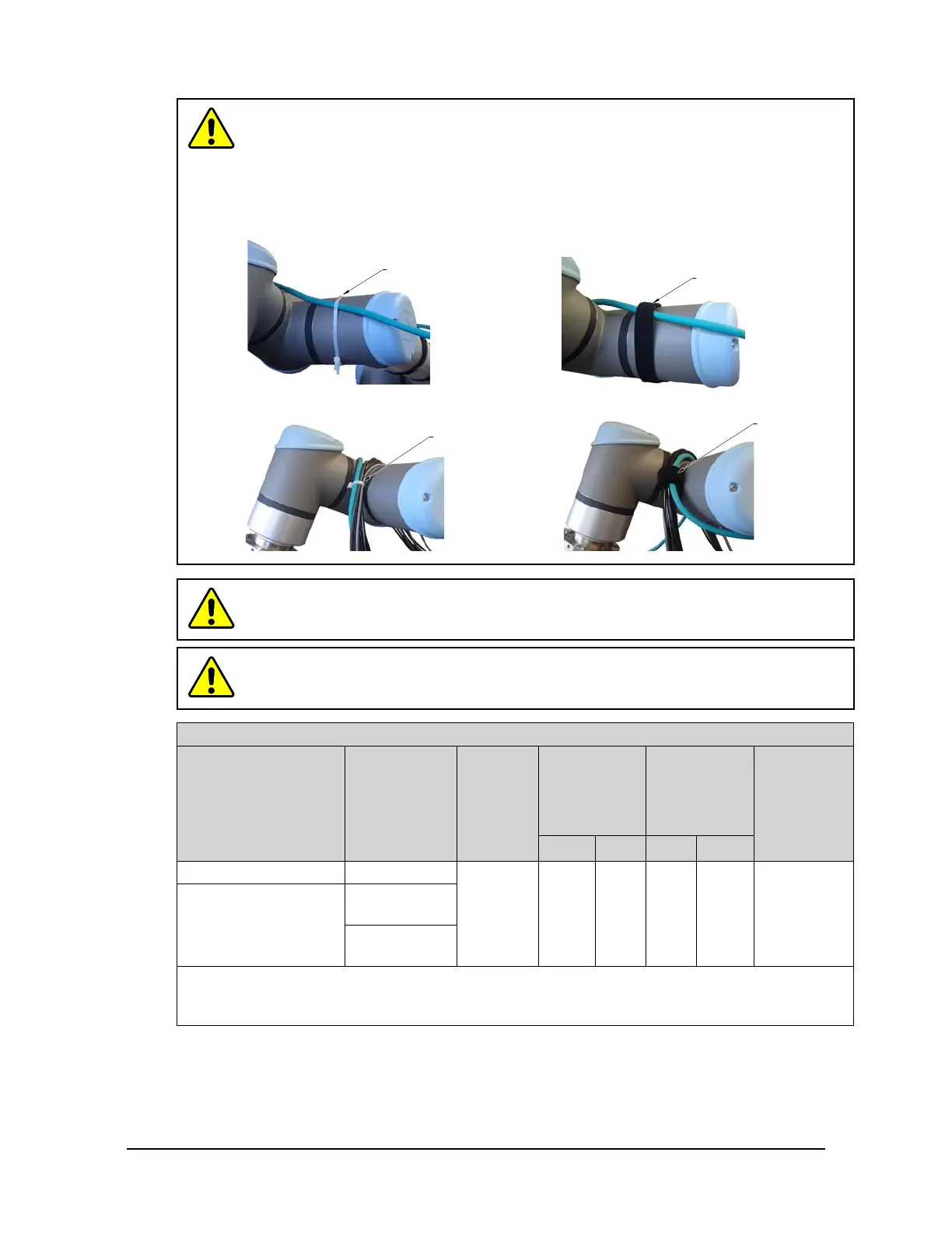
CAUTION: Do not cable ties or zip ties to bundle cables or restrain the cable to the
robotarm.Directlyafxingcabletiesorziptiestothecablejacketwillpreventpower
and signal communication between the F/T sensor and robot controller. Use hook
and loop or Velcro straps on the cable jacket surfaces. Examples of the incorrect and
correct methods to restrain or bundle cables are in the following pictures:
USE Velcro
®
straps to restrain
the cable around the robot arm.
DO NOT USE zip ties to restrain
the cable around the robot arm.
INCORRECT
CORRECT
USE Velcro
®
to bundle cables.
DO NOT USE zip ties
to bundle cables.
CAUTION: Do not damage or crush the cable by over tightening the
straps on the cable.
CAUTION: When routing the cables, do not bend less than the minimum bending
radiusspeciedinTable 3.1. A bend radius too small causes the cable to fail from
fatigue of the robot’s repetitive motion.
Table 3.1—Sensor Cable Bending Radius and Dynamic Twist Angle
Cable Part Number
Spliced Cable
Branch
Description
Cable
Diameter
mm (in)
Static
Bending
Radius
(at room
temperature)
Dynamic
Bending
Radius
(at room
temperature)
Dynamic
Cable Twist
Angle per
Unit Length
mm in mm in
9105-C-ZC22-ZC28-X N/A
6(.24) 25 1 50 2
180°/m or
55°/ft
9105-C-ZC28-U-
RJ45S-X
Branch 1,
Power
Branch 2,
Ethernet
Notes:
1. Temperatureaffectscableexibility.ATIrecommendsincreasingtheminimumdynamicbendingradiusfor
lower temperatures.
The 6-pin 9105-C-ZC22-ZC28-X cable attaches to the sensor’s connector. The 9105-C-ZC28-U-RJ45S-X
8-pin connector attaches to the 9105-C-ZC22-ZC28-X power and Ethernet cable. The 9105-C-ZC28-
U-RJ45S-X cable splits into the following (2) branches: an unterminated end for power and a RJ45
connection for Ethernet.

 Loading...