- 34 -
Electrical connections
Before performing any maintenance, make sure that all power supplies have been
cut off .
Electrical installation must be performed in accordance with current regulations.
The electrical diagram for the hydraulic unit is shown on fi g. 59, page 82.
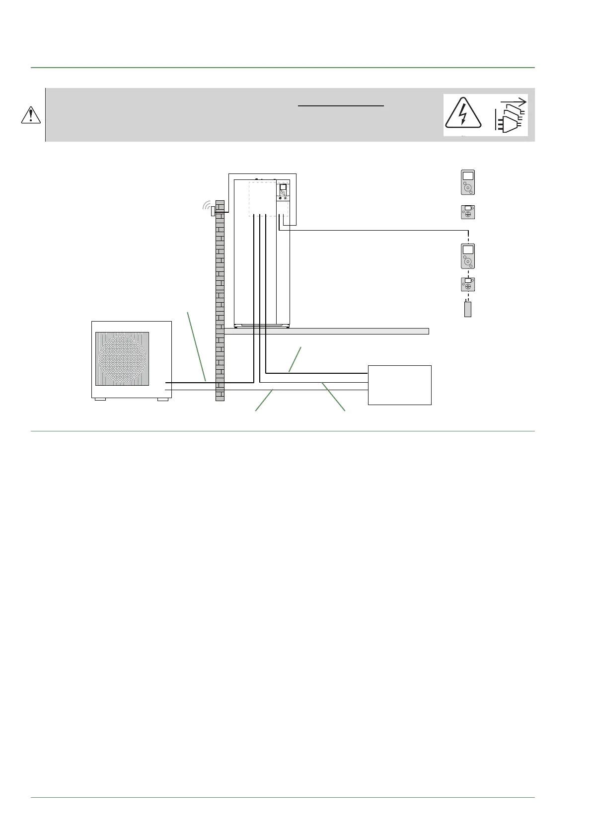
fi g. 39 - Overall layout of electrical connections for a simple installation (1 heating circuit)
Outside sensor
Cable 2 x 0.75 mm²
Connection outdoor unit and hydraulic unit
(phase, neutral, earth, communications bus)
Cable 4 G 1.5 mm²
Room sensor A78 (battery/option)
Room sensor A59 (battery/option)
Room sensor A75 (option)
Cable 2 x 0.5 mm²
Room sensor A59 (option)
Cable 2 x 0.5 mm²
Typass ATL (option)
Cable 3 x 0.5 mm²
Electrical backup power supply
(see table below)
DHW power supply
(phase, neutral, earth) Cable 3 G 1.5 mm²
General electrical supply (phase, neutral, earth)
(see table below)
Electrical
Board
or
or
or
or
Alfea Extensa A.I. R32 / INSTALLATION / 2114 - EN