- 38 -
►
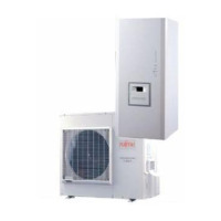
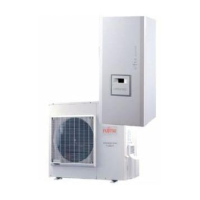
Hydraulic unit
Access to connection terminals:
- Remove the front plate.
- Open the power control box.
- Make the connections according to the diagram
(fi g. 45).
Do not place the sensor and power supply lines parallel
to each other to avoid interference due to voltage spikes
in the power supply.
Make sure that all electrical cables are housed in the
areas provided for this purpose.
▼
Interconnection between outdoor unit
and hydraulic unit
Match up the terminal block markers on the hydraulic
unit to those of the outdoor unit exactly when connecting
the interconnection cables.
An incorrect connection could result in the catastrophic
failure of one or other of the units.
▼
Electrical backup
If the heat pump is not installed with a boiler connection:
- Connect the power supply for the backup to the
electrical panel.
▼
Boiler connection (option)
- Please refer to the instructions supplied with the boiler
connection kit.
If the boiler connection option is used,
the electric backup must not be connected.
- Please refer to the instructions supplied with the boiler.
▼
Second heating circuit (option)
- Refer to the instructions supplied with the 2-zone
hydraulic circuit kit.
▼
Contract with Energy Supplier
The heat pump can be set to operate with diff erent
energy tariff s (eg off -peak, Solar photovoltaic (PV).In
particular, domestic hot water (DHW) at the comfort
temperature will be produced at off -peak times when
electricity is at its cheapest.
- Connect the "energy supplier" to the EX2 input (
fi g. 46,
page 43).
- Set the DHW confi guration to "Off -Peak".
• 230V on input EX2 = "Peak Hours” information
activated.
▼
Power limitation or EDR (Energy Demand
Reduction)
Power limitation is designed to reduce electricity
consumption during periods where electricity tariff s are
high or there is a limited electricity supply.
- Connect the power limiter device to input EX1 (fi g. 46,
page 43). Heat pump and DHW backups will be shut
off in the event of over-consumption by the dwelling.
• 230 V on input EX1 = power limitation in progress
During the power limitation or EDR, the
outdoor unit errors are not displayed on the
hydraulic unit.
▼
Faults external to the heat pump
Any component which reports back information
(Underfl oor heating safety switch, thermostat, pressure
switch, etc.) may signal an external problem and stop
the heat pump.
- Connect the external component to input EX3 (fi g. 46,
page 43).
• 230 V on input EX3 = heat pump stopped
(system displays Error 369).
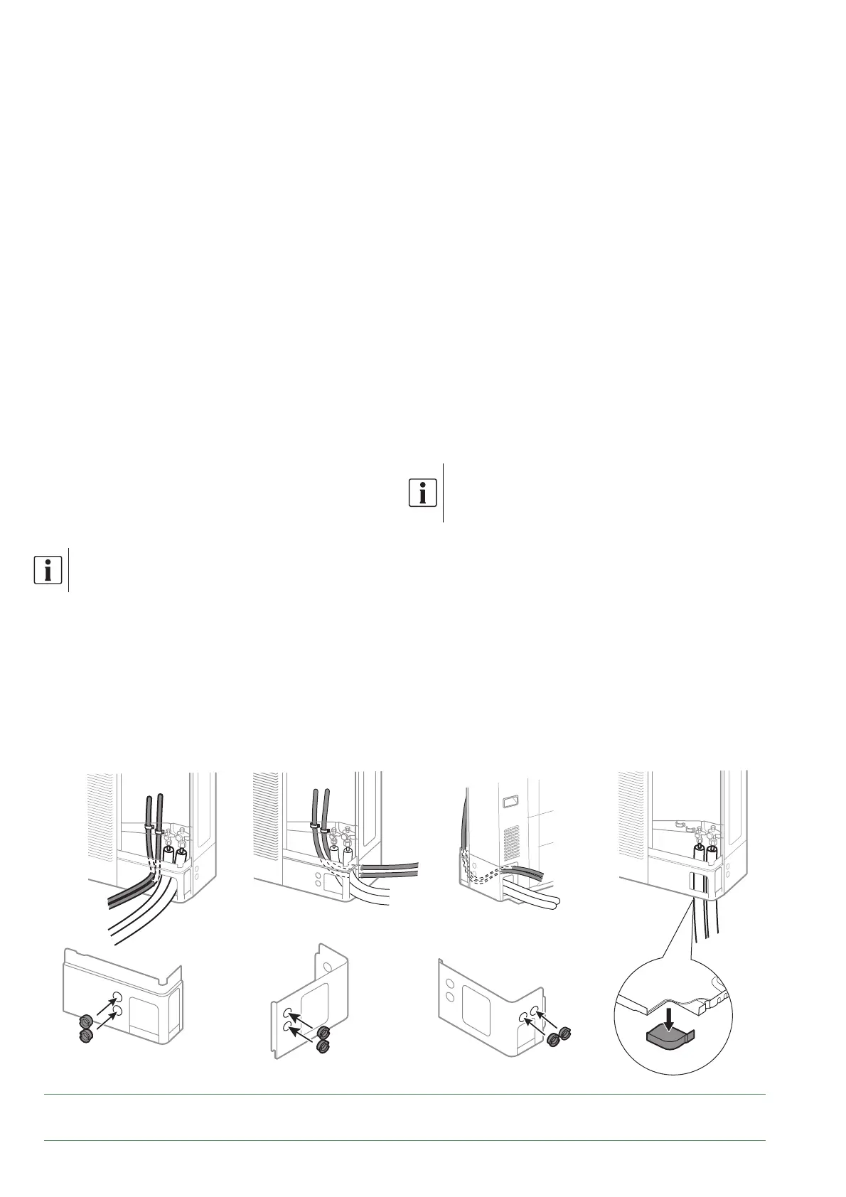
fi g. 43 - Location of electrical cables and refrigeration connections to outdoor unit (Model 10)
Devant Côté lateral Derrière
Inférieur
Front Lateral side Back Underneath
Alfea Extensa A.I. R32 / INSTALLATION / 2114 - EN