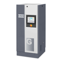
10 Operating instructions
10.1 Initial start up
Procedure
Always apply all relevant Safety precautions.
- Consult sections Installation proposal, Electric cable size and Settings of overload relay and fuses.
- Check that the electrical connections correspond to the applicable codes and that all wires are
clamped tight to their terminals.
The installation must be earthed and protected against short circuits by fuses of the inert type in all
phases. An isolating switch must be installed near the compressor.
- Check transformer (T1) for correct connection.
For Full-Feature units except for voltages 230 V and 400 V + N: check the dryer transformer (T2) for
correct connection.
Check the settings of drive motor overload relay (F21).
Check that the motor overload relay is set for manual resetting.
- Check the oil level. The sight glass (Gl) must be between 1/4 and 3/4 full. Add oil if necessary (see
section Oil and oil filter change).
- Provide labels, warning the operator that:
• The compressor is automatically controlled and may restart automatically.
• The compressor may automatically restart after voltage failure (if the function is activated -
consult Atlas Copco).
- The compressors are equipped with a phase sequence relay to protect the compressor from running
in the wrong direction.
Switch on the voltage and start the compressor.
If the compressor fails to start, check the display. If the display shows the pictograph for motor
overload, check the phase sequence relay.
If the rotation direction of the drive motor is incorrect or if the motor doesn't start, open the isolating
switch and reverse two incoming electric lines.
Incorrect rotation direction of the motor may cause damage to the compressor element.
- Check the programmed settings. Consult section Programmable settings.Programmable settings
- Start and run the compressor for a few minutes. Check that the compressor operates normally.
10.2 Starting
Procedure
Check the oil level, top up if necessary. See section Initial start up.
For the position of the air outlet valve and the drain connections, see sections Introduction.
Instruction book
2920 7140 90 127
 Loading...