2.6 Air dryer
Flow diagram
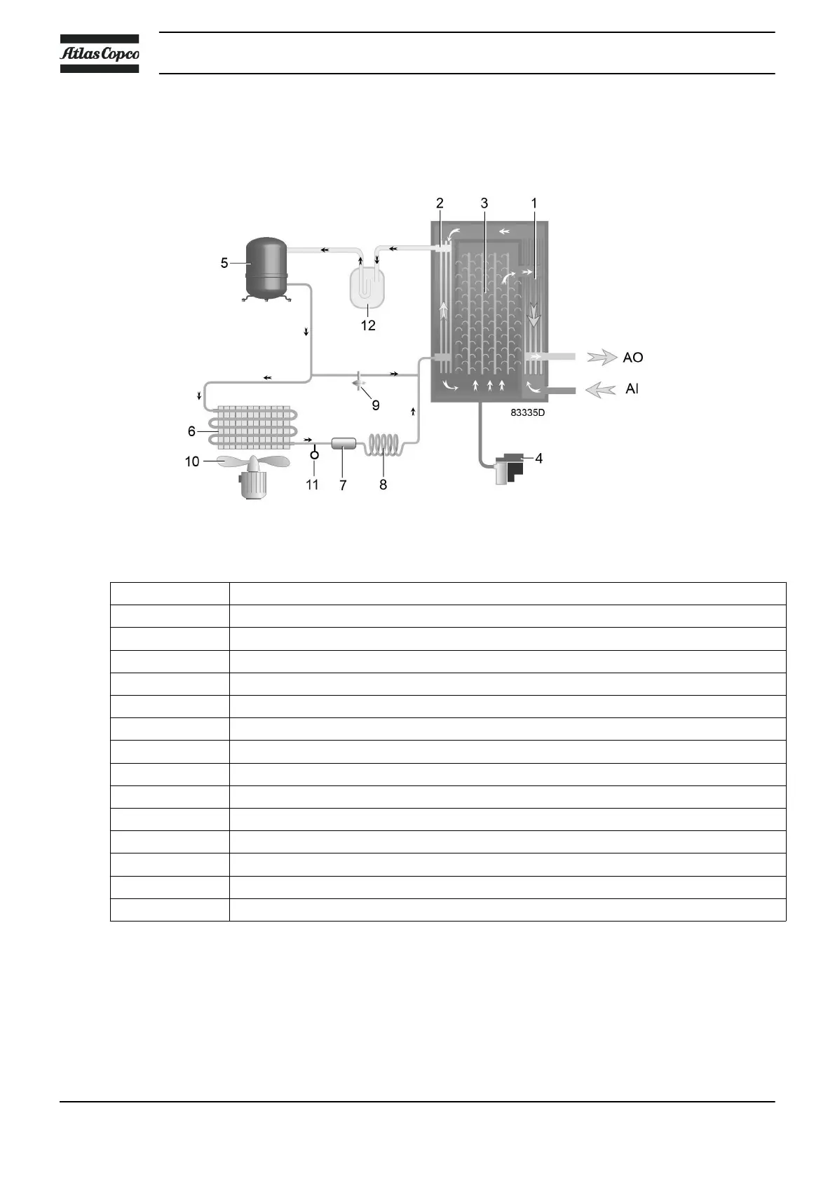
Air dryer
Reference Name
AI Air inlet
AO Air outlet
1 Air/air heat exchanger
2 Air/refrigerant heat exchanger/evaporator
3 Condensate separator
4 Automatic drain / condensate outlet
5 Refrigerant compressor
6 Refrigerant condenser
7 Liquid refrigerant dryer/filter
8 Capillary
9 Bypass valve
10 Condenser cooling fan
11 Pressure switch, fan control
12 Liquid separator
Compressed air circuit
Compressed air comes in the heat exchanger (1) and the outgoing, cold, dried air cools the incoming
compressed air.
Water in air starts to condense. Then, the air flows through the heat exchanger/evaporator (2), where the
refrigerant evaporates.
Instruction book
20 2920 7109 23

 Loading...
