Installation EN POWER FOCUS 600
6
© Atlas Copco Industrial Technique AB - 9836 6534 01
Installation
Installation Requirements
Installation checklist
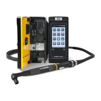
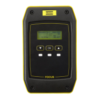
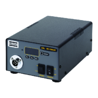
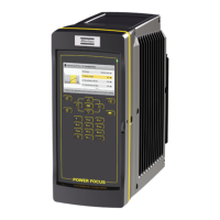
This POWER FOCUS 600 is a control and monitoring unit for electric assembly tools. The system
consists of:
■
a POWER FOCUS 600
■
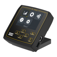
an IAM, Intelligent Application Module, containing software and configurations
■
a tool cable, available in different models and lengths
■
and a tool.
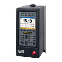
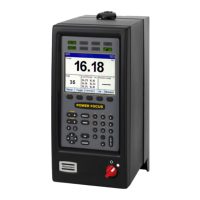
Connections – Front
Connections and switches on the Power Focus 600 controller.
1. Battery
2. Cable
3. USB port
4. IAM
5. Residual-current device (RCBO)
6. Aux. power out (24V, 1A)
7. Remote start
8. Digital input
9. EM Stop
10. Digital output
11. Factory Ethernet port
12. I/O Bus
13. Power connector
Installation Instructions
Installing the controller
The controller must be positioned so that the power switch is easily accessible.
For maximum tool performance ensure that the controller is mounted so that free airflow is provided.
This will improve the cooling of the controller.
1. Mount the mounting plate on the wall or steel plate with three M6 screws. If mounting on a wall, make
sure to use the correct wall bracket (plug and screw). If mounting on a steel plate, make sure that the
plate is at least 2 mm thick.
2. Attach the controller to the mounting plate by tilting the controller and then insert the top flange of the
mounting plate into the slot on the rear of the controller. Drop the controller down to engage the lock-
ing mechanism.
3. Mount the retainer strap between the wall and the cable cover.
4. Open the front access door of the controller.
5. Connect the power cable to the socket.
 Loading...