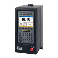
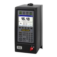
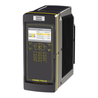
POWER FOCUS 600 EN Installation
© Atlas Copco Industrial Technique AB - 9836 6534 01
7
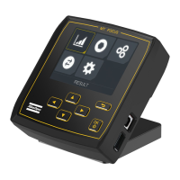
6. Connect the IAM to the socket on the back of the front access door.
7. Check that the RCBO (Residual-current device) is switched on
8. Close the front access door.
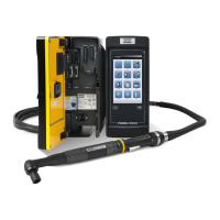
9. Connect the tool cable to the socket on the underside of the controller.
10. Connect the power cable to a power supply (115/230 V)
11. Turn the power switch on
Configuring remote start for single controller solutions
The switch for remote start is found on the connector board located behind the front access door.
Whenever enabling remote start you must for safety reasons implement an emergency stop solution.
When using portable hand-held or portable hand-guided tools (such as tools used with torque reac-
tion devices), remote start must be disabled by setting the switch on the controller to OFF. This is
done to make it impossible to override the safety function within the tools.
Emergency stop in Power Focus 600
Power Focus 600 is equipped with an emergency stop function with redundant breaking according to EN
ISO 13849-1 category 3 PL d. It provides a safe system that can be used with hand-held tools and sys-
tems.
The emergency stop function can be used with a supply disconnecting device (such as an EM Stop but-
ton). When pressed down, it breaks the supply voltage to the controller. The event 3040 Emergency stop
is displayed.
For the emergency stop and reset there is a 24 V DC output through the emergency stop terminal on the
connector board.
The cable connecting the EM Stop button to the controller is a 0.7 mm
2
cable with a maximum length of
400 meters.
Configuring emergency stop
The Power Focus has an external EM Stop interface on the connector board that is located behind the
front access door.
Connector: Phoenix, 6-pin Headers 3.5mm pitch
Use the following pin configuration:
Pin Function
1 Do not use
2 Do not use
3 EM STOP+
4 +24V
5 EM STOP -
6 +24V RET
Emergency stop button
The supply disconnecting device may serve as an emergency stop when it is readily accessible to the op-
erator and it is of the type described in EN 60204-1:2006, 5.3.2 a), b), c) or d). When intended for such
use, the supply disconnecting device shall be colored red and have a yellow background. (Ref. EN
60204-1:2006, 10.7.5).
 Loading...